Special valve for liquefied gas

A special valve, liquefied gas technology, applied in valve details, valve device, valve operation/release device, etc., can solve problems such as poor practicability, inability to filter dimethyl ether, bottlenecks in the efficiency of liquefied gas tanks, etc., to prevent The effect of gas leakage and easy control

Active Publication Date: 2020-12-04
黄友耐
View PDF12 Cites 0 Cited by
  • Summary
  • Abstract
  • Description
  • Claims
  • Application Information

AI Technical Summary

Problems solved by technology

[0003] The existing liquefied gas valve cannot filter the dimethyl ether in the liquefied gas inside the valve body, resulting in a bottleneck in the use efficiency of the existing liquefied gas tank and poor practicability

Method used


Image

  • Special valve for liquefied gas
  • Special valve for liquefied gas
  • Special valve for liquefied gas

Examples


Embodiment

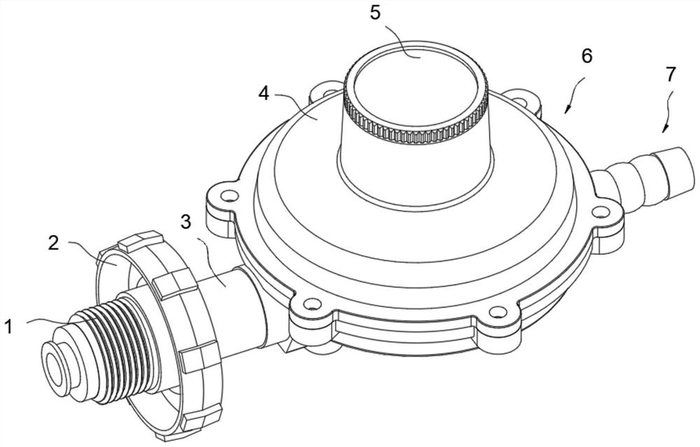
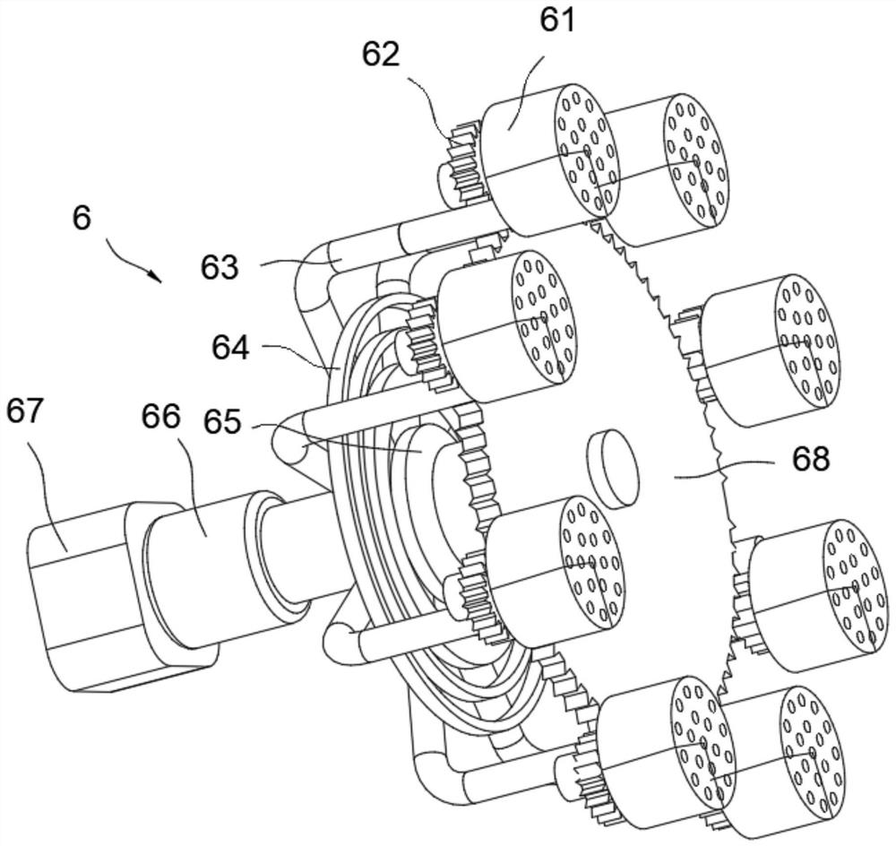
[0034] Embodiment: When using the special air valve, the electromagnet is first energized, and at this time the electromagnet will attract the permanent magnet. After the attraction, the flow path channel of the valve body 4 is opened, and the internal medium can be conducted at this time. , when the electromagnet is powered off, the permanent magnet will block the flow channel of the valve body 4, at this time the channel of the valve body will be reduced to the closed state synchronously, and the degree of opening and closing of the circulation channel will be determined by adjusting the energizing current of the electromagnet, thereby Determine the size of the flow rate, easy to control; when the adsorption device is working, first start to drive the air pump 66, which will bulge the reactant in the reactant box 67 out of the adsorption tube 63, and the adsorption tube 63 is provided with some through holes for The reactant is discharged, so that the fluid around the fixed p...


PUM


Abstract

The invention discloses a special valve for liquefied gas. The special valve for the liquefied gas comprises a valve body and is characterized in that a gas guide pipe is connected to one side of thevalve body in a through mode; a hoop is movably connected to the outer portion of the gas guide pipe through threads; an electromagnet is embedded into the hoop; a plurality of sliding grooves are formed in the inner wall of a threaded pipe; permanent magnets are connected into the sliding grooves in a sliding mode; the permanent magnets are of one-fourth circular disc-shaped structures and attract one another; an adsorption device is mounted in the valve body and comprises a reactant box; a driving air pump is fixed to one side of the reactant box through welding; a freeze-frame patch is fixed to one end of the driving air pump through a bolt; a main rotating disc is connected to one side of the freeze-frame patch; an adsorption pipe is fixed to one side of the freeze-frame patch throughwelding; and a planetary gear is fixed to the bottom of an adsorption filter through welding. The special valve for the liquefied gas has the characteristics of high practicability and good adsorptioneffect.

Description

technical field [0001] The invention relates to the technical field of valves, in particular to a special valve for liquefied gas. Background technique [0002] There are many types of special pressure reducing valves for liquefied petroleum gas, and the common ones are: pilot piston type pressure reducing valve, film type pressure reducing valve, bellows type pressure reducing valve, proportional pressure reducing valve, self-operated pressure reducing valve, direct acting piston type Pressure reducing valve, back pressure regulating valve, etc. They are respectively suitable for different working media. [0003] The existing liquefied gas valve cannot filter the dimethyl ether in the liquefied gas inside the valve body, resulting in a bottleneck in the use efficiency of the existing liquefied gas tank and poor practicability. Therefore, it is necessary to design a special valve for liquefied gas with a practical cavity and good adsorption effect. Contents of the invent...

Claims


Application Information

Patent Timeline
IPC IPC(8): F16K31/08B01D49/00F17C13/04F17C13/06B65C9/18
CPCF16K31/082F16K31/0644B01D49/00F17C13/04F17C13/06B65C9/18
Inventor 黄友耐
Owner 黄友耐
Why Eureka
Try Eureka