
Constant-temperature circulating valve and mounting and using method thereof

A circulating valve and constant temperature technology, applied in the valve device, valve operation/release device, application, etc., can solve the problems such as the inability to effectively prevent the growth of Legionella, the temperature of the circuit water, and the uneven heating and cooling of the water outlet.

Pending Publication Date: 2020-12-04
班尼戈管路系统(宁波)有限公司
View PDF0 Cites 1 Cited by
  • Summary
  • Abstract
  • Description
  • Claims
  • Application Information

AI Technical Summary

Problems solved by technology

[0005] The purpose of the present invention is to solve the problems of uneven cooling and heating at each outlet and high energy consumption in the traditional hot water system, which brings great troubles to the user's comfort, safety and operation and maintenance costs. Moreover, it cannot ensure that each hot water circulation branch of the water supply system can reach the required temperature, and it cannot effectively prevent the growth of Legionella, and the problem of uneven water temperature in the circuit occurs. A constant temperature circulation valve and its installation and use method are proposed

Method used


Image

  • Constant-temperature circulating valve and mounting and using method thereof
  • Constant-temperature circulating valve and mounting and using method thereof
  • Constant-temperature circulating valve and mounting and using method thereof

Examples


Embodiment 1

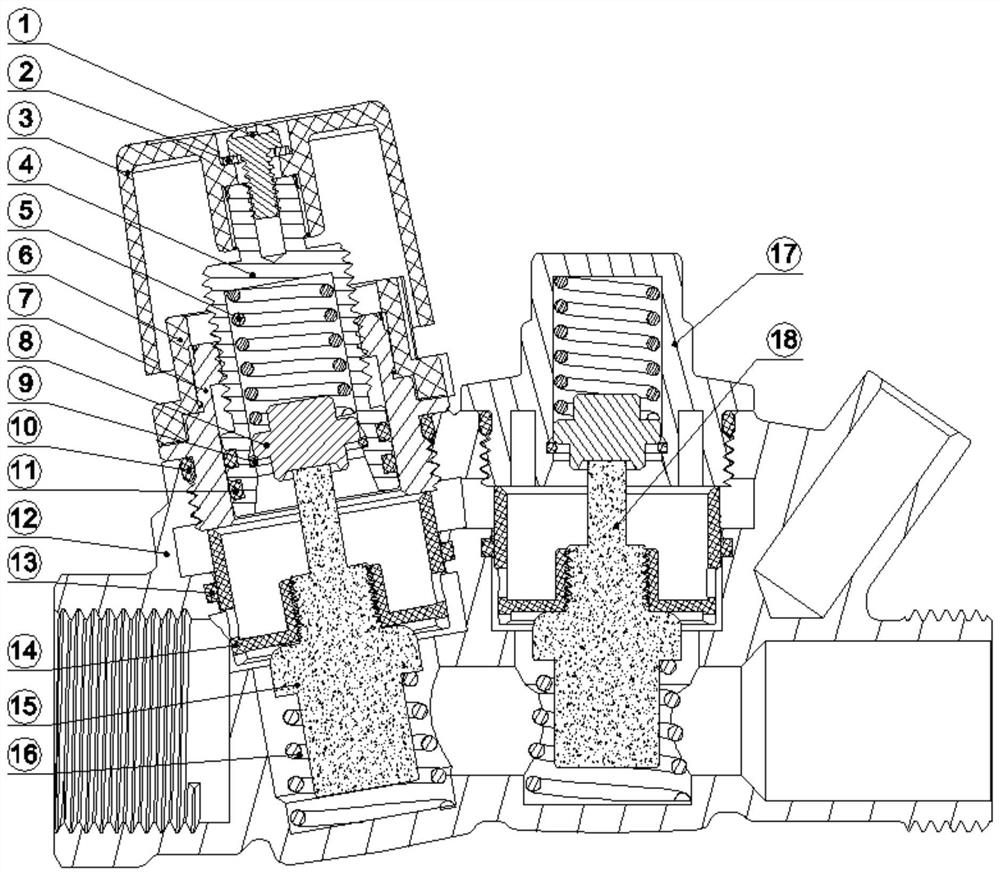
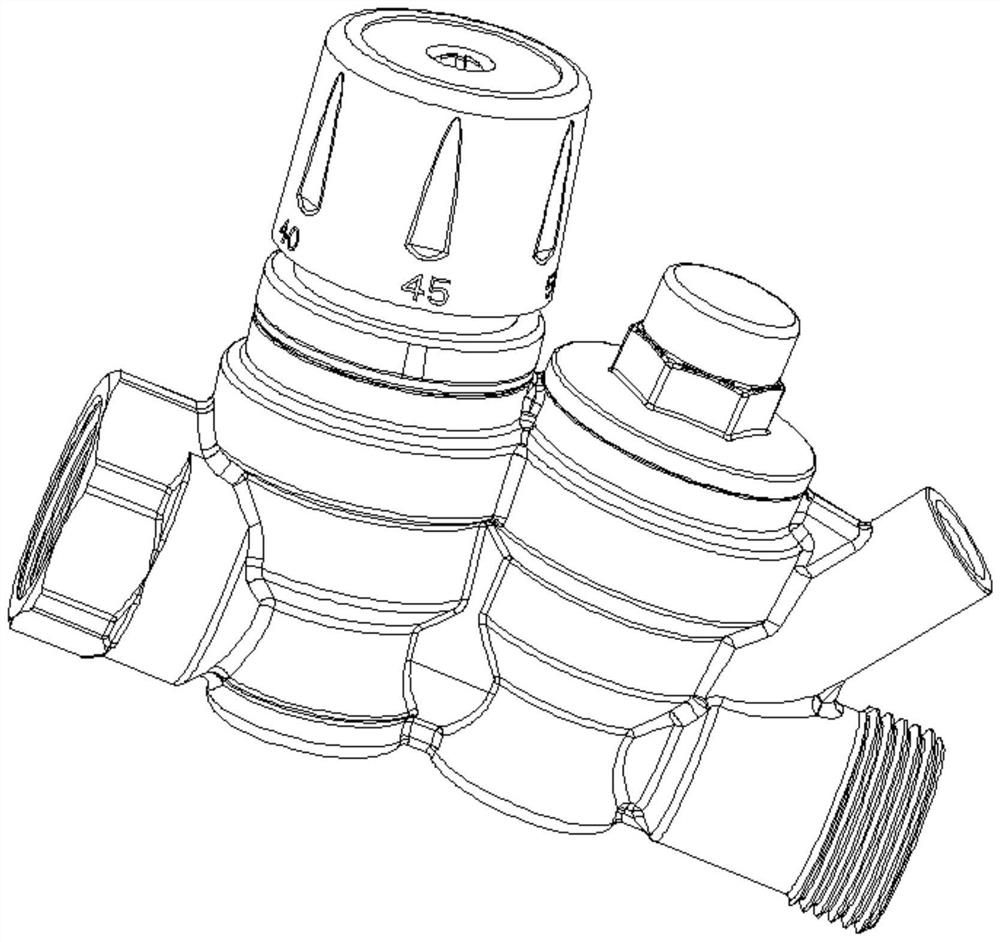
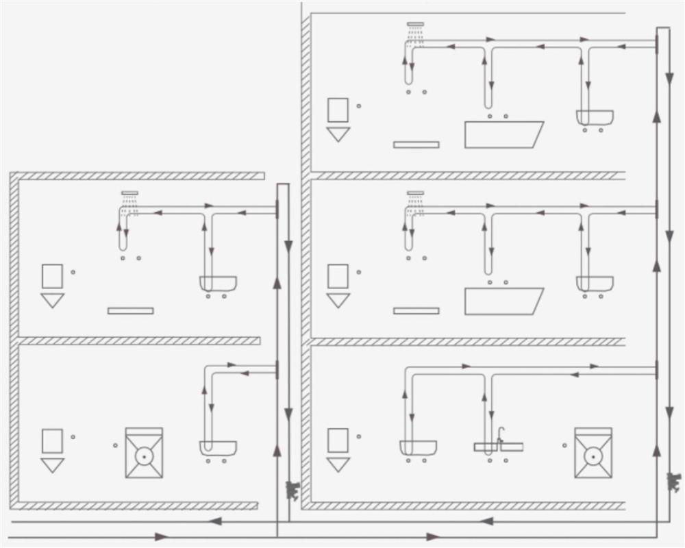
[0034] refer to Figure 1-5 , a constant temperature circulation valve, including a valve body 12, the valve body 12 is respectively provided with a temperature regulating package 15 and a sterilization temperature package 18, and the lower ends of the temperature regulation package 15 and the sterilization temperature package 18 are both provided with a working spring 16 to adjust the temperature The middle of the bag 15 and the sterilization temperature bag 18 are respectively provided with a control piston 14 and a bypass piston. The built-in temperature control bag 15 automatically adjusts the flow through the valve body 12 according to the water temperature. When the water temperature is close to the set temperature, the temperature is adjusted. Packet 15 gradually reduces the flow, so that the circulation system flow can be distributed to other outlets of the system to achieve the effect of rapid constant temperature balance flow. The upper ends of the regulating temperat...


PUM


Abstract

The invention discloses a constant-temperature circulating valve. The constant-temperature circulating valve comprises a valve body, an adjusting temperature bulb and a sterilizing temperature bulb are arranged in the valve body, the lower end of the adjusting temperature bulb and the lower end of the sterilizing temperature bulb are each sleeved with a working spring, the middle of the adjustingtemperature bulb and the middle of the sterilizing temperature bulb are sleeved with a control piston and a bypass piston respectively, and the upper end of the adjusting temperature bulb and the upper end of the sterilizing temperature bulb are each fixedly connected with a spring seat. According to the constant-temperature circulating valve and the mounting and using method thereof, in a domestic hot water system, in order to ensure that each hot water circulating branch of a water supply system reaches the required temperature, ensure that hot water can be used immediately after being opened and effectively prevent legionella breeding, the flow of a circulating loop is adjusted so that the phenomenon of different loop water temperatures can be avoided, the design of different-stroke loops with automatic balance of the hot water system is realized, the pipeline investment is reduced, more comfortable experience is realized, the thermal sterilization requirement can be met, and a settemperature can be automatically maintained when the constant-temperature circulating valve is installed in each loop of the hot water circulation system.

Description

technical field [0001] The invention relates to the technical field of a constant temperature circulation valve system, in particular to a constant temperature circulation valve and an installation and use method thereof. Background technique [0002] Studies have shown that under the condition of water temperature ≤ 45°C, the bacterial reproduction rate is accelerated and the risk of microbial contamination increases. Among them, Legionella pneumophila has the characteristics of multiplying in the water supply system and has a high pathogenicity rate. The World Health Organization and other countries have listed it as the number one threat. Especially in the hot water circulation system, people must pay great attention to it. Low water temperature, low flow rate, biofilm, stagnant water areas, etc. are all favorable conditions for the growth of Legionella. [0003] Traditional hot water systems often have problems such as uneven cooling and heating at each water supply end...

Claims


Application Information

Patent Timeline
IPC IPC(8): F16K11/20F16K31/68F16L59/16F24D19/10
CPCF16K11/20F16K31/002F16L59/161F24D19/10
Inventor 朱红松祝瑜艇
Owner 班尼戈管路系统(宁波)有限公司
Learn More