Al technical title is built by PatSnap Al team. It summarizes the technical point description of the patent document.
A printing press and printmaking technology, applied in the field of printmaking printing presses, can solve the problems of unshaped printed objects and other problems
Inactive Publication Date: 2020-12-04
刘清杰
View PDF0 Cites 1 Cited by
Summary
Abstract
Description
Claims
Application Information
AI Technical Summary
This helps you quickly interpret patents by identifying the three key elements:
Problems solved by technology
Method used
Benefits of technology
Problems solved by technology
[0004] Its prints are coated with colorant in liquid form. After the printed object is placed on the top for pressing, it needs to be separated. Objects don't take shape
Method used
Image
Click on the blue label to locate the original text in one second.
Reading with bidirectional positioning of images and text.
Examples
Embodiment 1
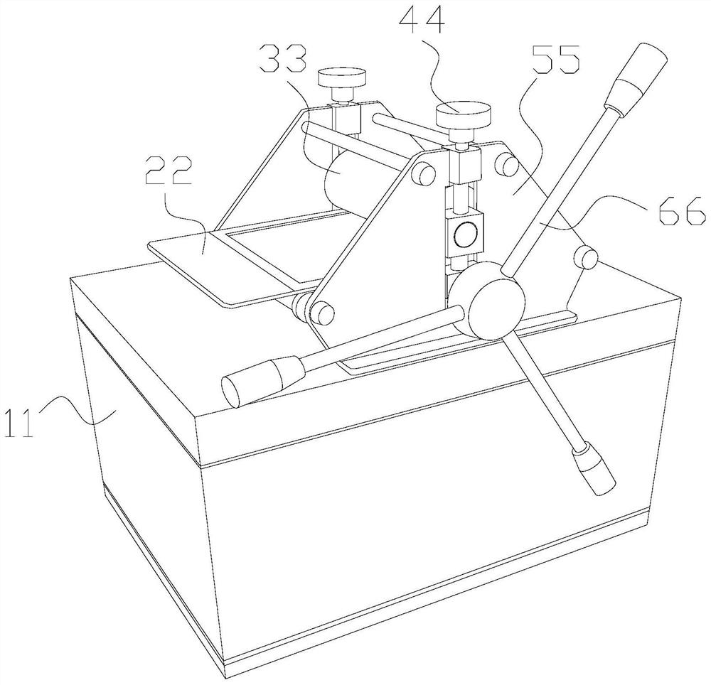
[0032] as attached figure 1 to attach Image 6 Shown:
[0033] The present invention provides an engraving printing machine, the structure of which comprises a bottom box 11, a bottom platen 22, a roller 33, a height adjustment rod 44, a side support plate 55, and a rotating rod 66, and the side support plate 55 is vertically welded to the bottom box 11 On the upper surface, side support plates 55 are installed at both ends of the roller body 33, the height adjustment rod 44 is fixedly connected with the side support plate 55, the bottom pressure plate 22 is located below the roller body 33, and the rotating rod 66 is connected to the height adjustment rod 55. Rod 44 is connected.
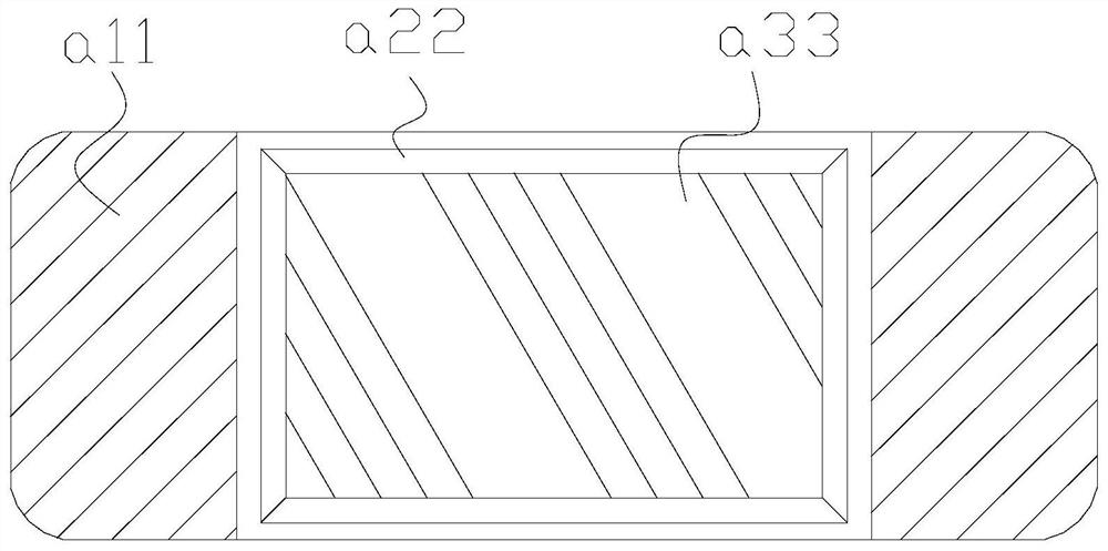
[0034] The bottom platen 22 includes an extension plate a11, a glue port a22, and a built-in groove a33. The built-in groove a33 and the extension plate a11 are an integrated structure, and the glue hole a22 is installed on the inner wall of the built-in groove a33.
[0035] Wherein, the rubber ...
Embodiment 2
[0042] as attached Figure 7 To attach Figure 9 Shown:
[0043] Wherein, the epitaxial layer e22 includes a support body x10 and a spacer bar x20, the spacer bar x20 is installed between two support bodies x10, there are two spacer bar x20, and the spacer bar x20 The supporting body x10 bears external force in a large area at intervals at the overall stress-bearing part.
[0044] Wherein, the support x10 includes an outer covering g1, a corner g2, and a soft corner core g3, the corner g2 is attached to the outer surface of the soft corner core g3, and the soft corner core g3 is embedded inside the outer wrapping body g1 , the soft angle core g3 is a triangular structure, the interval angle g2 is a V-shaped structure, the interval angle g2 guides the stress tendency of the spaced parts, and the outer covering g1 limits the installation range of the inner parts.
[0045] Wherein, the soft corner core g3 includes a coating layer s11 and a soft elastic core s22. The soft elast...
PUM
Abstract
The invention discloses a pattern printing machine. The structure of the print printing machine comprises a bottom box, a bottom pressing plate, a rolling body, a height adjusting rod, side supportingplates and a rotating rod; the side supporting plates are vertically welded to the upper surface of the bottom box, the side supporting plates are installed at the two ends of the rolling body, and paper needing to be printed is moved between bayonets of a glue opening to be clamped and fixed through clamping balls, so that a counterforce effect is achieved on an extrusion part; compression deformation is carried out through an empty opening, when the clamping balls are stressed, the clamping balls are fixedly supported, the position of a fixed core of an inner core is fixed, and the rollingbody is moved away so that corners of paper can be vertically separated at the same time when the paper is pressed on a duplicate engraving plate for printing and is separated, the paper cannot be rubbed, and the whole part is uniformly separated by force separating strips, and the stressed force is uniformly separated; and the outer layer of a supporting body is wrapped by an outer wrapping body,so that the mounting range of an inner part is limited, the counter force on the two sides can be supported, and the external force of an auxiliary fixing part can be internally released and uniformly separated when the auxiliary fixing part is stressed and pressed.
Description
technical field [0001] The invention belongs to the field of printing machines, and more specifically relates to an engraving printing machine. Background technique [0002] The engraving printing is to place the engraved template on the bottom, apply the coloring agent evenly on the engraving, press the part to be printed on the engraving, and roll and move the pressing through the upper part, so that it can be colored on the engraving. On the printed object, it is enough to separate the two. [0003] Based on the above-mentioned inventor's discovery, existing print printing machines mainly have the following deficiencies, such as: [0004] Its prints are coated with colorant in liquid form. After the printed object is placed on the top for pressing, it needs to be separated. Objects don't take shape. [0005] Therefore need to propose a kind of engraving printing machine. Contents of the invention [0006] In order to solve the above-mentioned technology, the colorin...
Claims
Application Information
Patent Timeline
Application Date:The date an application was filed.
Publication Date:The date a patent or application was officially published.
First Publication Date:The earliest publication date of a patent with the same application number.
Issue Date:Publication date of the patent grant document.
PCT Entry Date:The Entry date of PCT National Phase.
Estimated Expiry Date:The statutory expiry date of a patent right according to the Patent Law, and it is the longest term of protection that the patent right can achieve without the termination of the patent right due to other reasons(Term extension factor has been taken into account ).
Invalid Date:Actual expiry date is based on effective date or publication date of legal transaction data of invalid patent.