
Annular workpiece milling, grinding and measuring integrated machining machine tool and control method thereof

A technology for processing ring workpieces and machine tools, which is applied in computer control, program control, general control systems, etc., and can solve problems such as difficulty in processing high-precision ring parts, large processing errors, and difficulty in meeting precision requirements for ring parts.

Active Publication Date: 2020-12-04
JILIN UNIV
View PDF12 Cites 2 Cited by
  • Summary
  • Abstract
  • Description
  • Claims
  • Application Information

AI Technical Summary

Problems solved by technology

[0003] The invention aims at the troublesome positioning of the ring-shaped workpiece in the process of machine tool processing. It is easy to deform due to the clamping force during clamping, and it will be deformed due to the force applied by the tool or grinding head during processing, resulting in large processing errors. The processed ring parts Difficult to meet the precision requirements, high scrap rate, many clamping times, cumbersome operation, difficult to process high-precision ring parts and other problems, a ring workpiece milling, grinding and measuring integrated processing machine tool and its control method are proposed

Method used


Image

  • Annular workpiece milling, grinding and measuring integrated machining machine tool and control method thereof
  • Annular workpiece milling, grinding and measuring integrated machining machine tool and control method thereof
  • Annular workpiece milling, grinding and measuring integrated machining machine tool and control method thereof

Examples


Embodiment Construction

[0048] The technical scheme of the present invention is further described below in conjunction with accompanying drawing and embodiment:

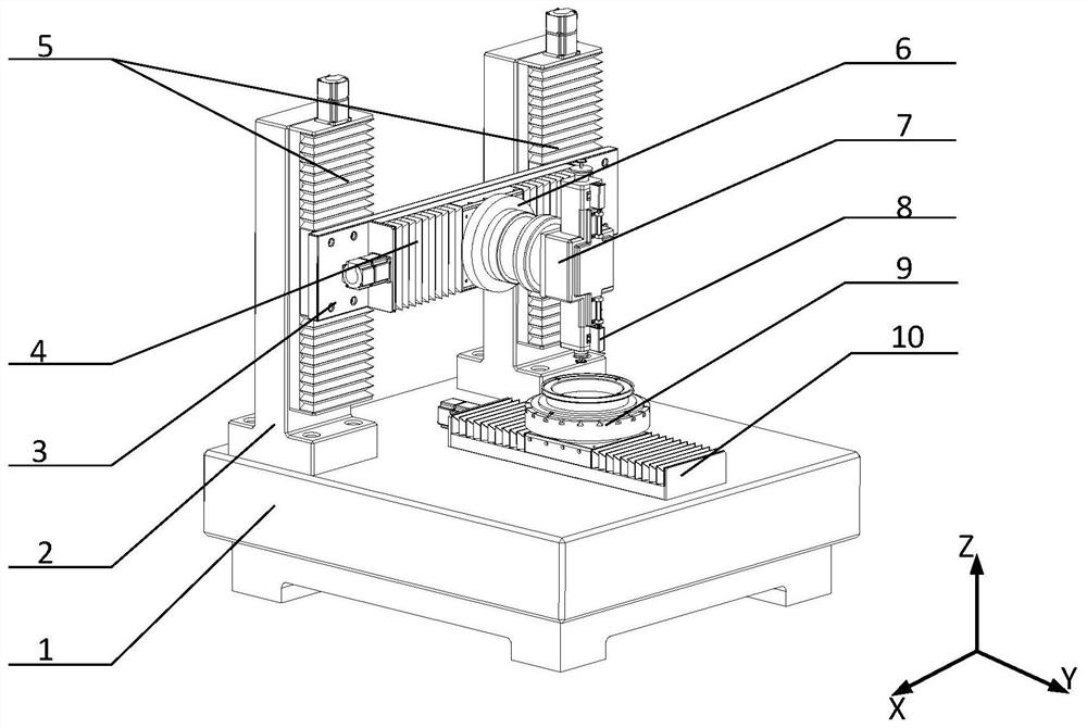
[0049] Such as figure 1 As shown, a circular workpiece milling, grinding and measuring integrated processing machine tool includes a machine base 1, a Z-axis mounting support 2, an X-axis mounting panel 3, an X-axis moving device 4, a Z-axis moving device 5, and a B-axis rotating table 6. Milling and grinding operation system 7, measuring mechanism 8, worktable 9 and Y-axis moving device 10; Z-axis mounting support 2 is fixed on the machine tool base 1, and Z-axis moving device 5 is fixed on Z-axis mounting support 2 , the X-axis mounting panel 3 is fixed on the Z-axis moving device 5 and driven by the Z-axis moving device 5 to move up and down along the Z-axis direction, the X-axis moving device 4 is fixed on the X-axis mounting panel 3, and the B-axis rotating table 6 is fixed On the X-axis moving device 4 and driven by the X-axis moving...


PUM


Abstract

The invention discloses an annular workpiece milling, grinding and measuring integrated machining machine tool which comprises a machine tool base, a Z-axis mounting support, an X-axis mounting panel,an X-axis moving device, a Z-axis moving device, a B-axis rotating table, a milling and grinding operation system, a measuring mechanism, a workbench and a Y-axis moving device. The Z-axis mounting support is fixed to the machine tool base, the Z-axis moving device is fixed to the Z-axis mounting support, the X-axis mounting panel is fixed to the Z-axis moving device and is driven by the Z-axis moving device to move up and down in the Z-axis direction, and the X-axis moving device is fixed to the X-axis mounting panel. The B-axis rotating table is fixed to the X-axis moving device and drivenby the X-axis moving device to move leftwards and rightwards in the X-axis direction, the milling and grinding operation system is fixed to the B-axis rotating table, the measuring mechanism is fixedto the end of the milling and grinding operation system, the workbench is fixed to the Y-axis moving device and driven by the Y-axis moving device to move forwards and backwards in the Y-axis direction, and the Y-axis moving device is fixed to the machine tool base. Meanwhile, the invention discloses a control method of the annular workpiece milling, grinding and measuring integrated machining machine tool.

Description

technical field [0001] The invention relates to a ring workpiece milling, grinding and measuring integrated processing machine tool and a control method thereof, which belong to the technical field of mechanical manufacturing. Background technique [0002] With the development of society and the advancement of science and technology, the mechanical equipment used in various industries is becoming more and more sophisticated and complex, and the processing accuracy required by the corresponding parts is also getting higher and higher. There are a large number of applications in equipment, especially high-precision ring parts, which play an important role in some high-tech fields, such as medical, aerospace and military. During manufacturing and processing, the ring-shaped workpieces corresponding to the ring parts are short hollow cylinders, and some of the ring-shaped workpieces have thinner walls, which are not easy to clamp and position, and are prone to deformation due to...

Claims


Application Information

Patent Timeline
Patent Type & Authority Applications(China)
IPC IPC(8): B23P23/04G05B19/404
CPCB23P23/04G05B19/404
Inventor 冀世军孙仍权赵继贺秋伟胡志清代汉达
Owner JILIN UNIV
Learn More