
A precision surveying and mapping device for engineering surveying

A surveying and mapping device and engineering surveying technology, applied in the field of surveying and mapping instruments, can solve problems such as time-consuming adjustment of instrument level, insufficient platform level accuracy, and influence of surveying and mapping data accuracy, etc., to achieve reduced leveling difficulty, light weight, easy fixation and release Effect

Active Publication Date: 2022-03-04
昆山市城乡房产测量有限公司
View PDF0 Cites 0 Cited by
  • Summary
  • Abstract
  • Description
  • Claims
  • Application Information

AI Technical Summary

Problems solved by technology

[0003] At present, it is necessary to use various instruments in surveying and mapping, such as theodolite, level and distance meter, etc., and a support frame for supporting surveying and mapping instruments is required; because the ground conditions of the surveying and mapping site are relatively complicated, or uneven, or have large and small Slopes, after the surveying and mapping instruments at this stage are installed on the support frame, they need to adjust the level of the platform through several adjustment screws to ensure the horizontal accuracy of the instrument and the accuracy of the surveying and mapping data. However, the erection of the support frame depends entirely on I feel that the adjustment accuracy of the support feet is low, which leads to insufficient level accuracy of the platform used to install the surveying and mapping instruments on the support frame. Accuracy makes a difference

Method used


Image

  • A precision surveying and mapping device for engineering surveying
  • A precision surveying and mapping device for engineering surveying
  • A precision surveying and mapping device for engineering surveying

Examples


Embodiment Construction

[0031] The technical solutions in the embodiments of the present invention will be clearly and completely described below with reference to the accompanying drawings in the embodiments of the present invention. Obviously, the described embodiments are only a part of the embodiments of the present invention, but not all of the embodiments. Based on the embodiments of the present invention, all other embodiments obtained by those of ordinary skill in the art without creative efforts shall fall within the protection scope of the present invention.

[0032] Unless otherwise defined, technical or scientific terms used in this disclosure shall have the ordinary meaning as understood by one of ordinary skill in the art to which this disclosure belongs. As used in this disclosure, "comprises" or "comprising" and similar words mean that the elements or things appearing before the word encompass the elements or things recited after the word and their equivalents, but do not exclude other...


PUM


Abstract

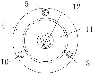
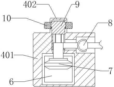
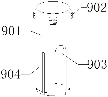
The invention provides a precise surveying and mapping device for engineering surveying, which includes a support frame, the support frame includes a base and telescopic rods, at least three telescopic rods are arranged in a circle on the bottom side of the base, the base is in the shape of a ring, and the base is provided with Horizontal adjustment mechanism, the central through hole of the ring structure of the base is provided with a mounting plate, the mounting plate is movably connected with the base through the horizontal adjustment mechanism structure protruding from the inner side wall of the base, the middle position of the mounting plate is provided with connecting screws, the mounting plate The upper end is equipped with a surveying instrument through a connecting screw, the base of the present invention is set separately from the mounting plate, and the floating block is movably connected with the ball cage connecting piece. After the fixing of the floating block is released, the floating block will drive the mounting plate under the action of buoyancy The activity makes the mounting plate closer to the horizontal state, provides a more horizontal installation environment, reduces the difficulty of subsequent leveling of the surveying instrument, improves the horizontal accuracy of the surveying instrument, and thus obtains more accurate surveying and mapping data, which has a good development prospect.

Description

technical field [0001] The invention relates to the field of surveying and mapping instruments, in particular to a precise surveying and mapping device for engineering measurement. Background technique [0002] Architectural planning refers to the design to meet certain construction purposes (including people's requirements for its use function and its visual experience). Area, slope inclination angle and actual topography and other data are used for fixed-point surveying and mapping, and the surveying and mapping results are used as the basis for architectural planning. [0003] At present, various types of instruments, such as theodolites, spirit levels and rangefinders, are required for surveying and mapping, and a support frame is required to support the surveying and mapping instruments; due to the complex ground conditions of the surveying and mapping site, it may be uneven or large or small. Slope, after the current surveying and mapping instrument is installed on th...

Claims


Application Information

Patent Timeline
Patent Type & Authority Patents(China)
IPC IPC(8): G01C15/00F16M11/04F16M11/18F16M11/16F16M11/32
CPCF16M11/04F16M11/18F16M11/16F16M11/32G01C15/00
Inventor 戴云云
Owner 昆山市城乡房产测量有限公司
Learn More