Base station antenna for mobile communication network engineering

A technology of mobile communication network and base station antenna, which is applied in the field of base station antenna equipment and can solve problems such as unstable installation

Pending Publication Date: 2020-11-27
重庆桦秀科技有限公司
View PDF1 Cites 0 Cited by
  • Summary
  • Abstract
  • Description
  • Claims
  • Application Information

AI Technical Summary

Problems solved by technology

At present, after analysis, it is found that most of the base station antennas are not installed firmly, because the signal coverage of the base station antenna is affected by its installation height, so we make improvements to this and propose a mobile communication network project with firm installation base station antenna

Method used


Image

  • Base station antenna for mobile communication network engineering
  • Base station antenna for mobile communication network engineering
  • Base station antenna for mobile communication network engineering

Examples


Embodiment 1

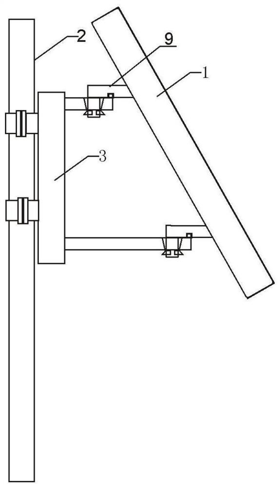
[0023] Embodiment 1, a base station antenna for mobile communication network engineering, including a group of antenna bodies 1, same as realizing mobile communication;

[0024] It also includes a set of communication tower brackets 2 for supporting the antenna body 1;

[0025] It also includes a group of communication antenna carrying units 3 for carrying the antenna body 1 .

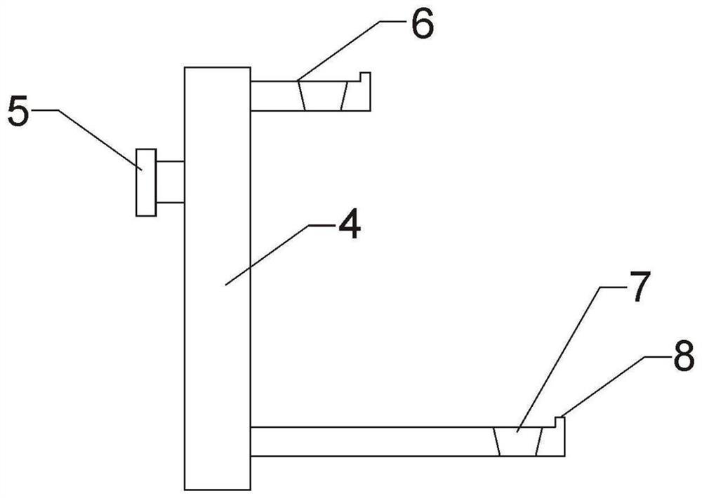
[0026] During implementation, the communication antenna carrying unit 3 includes a carrying wall plate 4, and a clamp 5 is provided on the back of the carrying wall plate 4; two upper and lower wall hanging ends 6 are also fixed on the carrying wall plate 4;

[0027] In practice, the wall hanging end 6 has a slot 7, and the side of the slot 7 has an upward opening protrusion 8;

[0028] During implementation, the communication antenna bearing unit 3 is fixed on the communication tower bracket 2 through a clamp 5 .

Embodiment 2

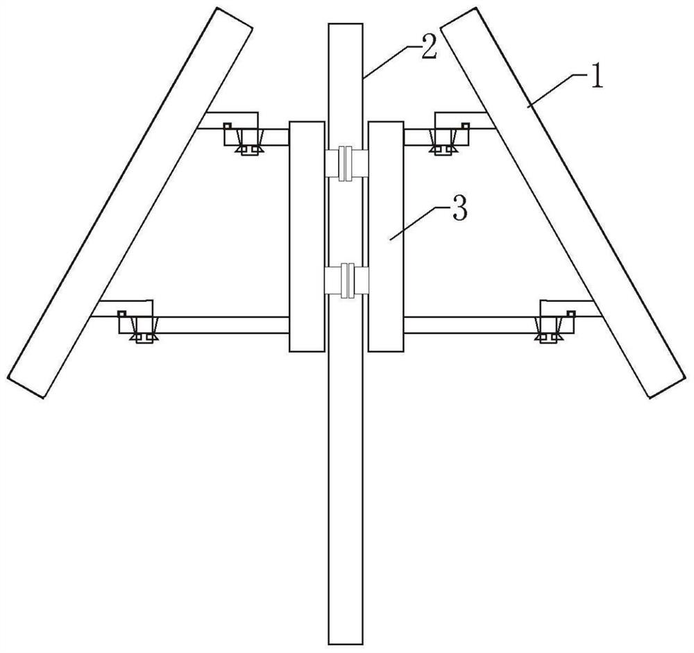
[0029] Embodiment 2, a base station antenna for mobile communication network engineering, including two sets of antenna bodies 1, same as for realizing mobile communication;

[0030] It also includes a set of communication tower brackets 2 for supporting the antenna body 1;

[0031] It also includes two sets of communication antenna carrying units 3 for carrying the antenna body 1;

[0032] The two groups of antenna bodies 1 are fixed by the corresponding communication antenna bearing units 3, and the two groups of communication antenna bearing units 3 are fixed back-to-back on the communication tower bracket 2 through the clamps 5;

[0033] The communication antenna bearing unit 3 includes a load-bearing wall plate 4, and a clamp 5 is arranged on the back of the load-bearing wall plate 4; two upper and lower wall hanging ends 6 are also fixed on the load-bearing wall plate 4;

[0034] The wall hanging end 6 has a slot 7, and the side of the slot 7 has an upward opening protr...


PUM


Abstract

The invention discloses a base station antenna for mobile communication network engineering. The base station antenna comprises a group of antenna bodies. The base station antenna further comprises agroup of communication tower brackets. The antenna also comprises a group of communication antenna bearing units. During implementation, the communication antenna bearing unit comprises a bearing wallplate, and a hoop is arranged on the back surface of the bearing wall plate. An upper wall-mounted end part and a lower wall-mounted end part are also fixed on the bearing wall plate. In the implementation process, the wall hanging end is provided with an inserting groove, and the side face of the inserting groove is provided with an upward opening protrusion. The back side of the antenna body isarranged in the corresponding slot through a clamping strip. During implementation, the communication antenna bearing unit is fixed on a communication tower support through a hoop. The base station antenna has the following advantages; the base station antenna has the advantages of being simple in overall structure, convenient to assemble and disassemble, stable in overall structure and the like;(2) during assembly, the back side of the antenna body is arranged in the corresponding slot through the clamping strip, the implementation is simple, the operation is convenient, and the insertion connection can be quickly realized; and (3) the whole base station antenna has better stability and guidance quality.

Description

technical field [0001] The invention relates to a base station antenna device, in particular to a base station antenna for mobile communication network engineering. Background technique [0002] In the engineering design of mobile communication network, base station antennas should be reasonably selected according to actual conditions such as network coverage requirements, traffic distribution, anti-interference requirements, and network service quality. The traffic distribution is closely related, and the antenna usage environment can be roughly divided into five types: urban areas, dense urban areas, suburban areas, rural areas, and traffic arteries. After searching, it was found that the utility model with application number CN201920685165.5 discloses a base station antenna, including a communication tower bracket and an antenna body. Two clamps are arranged outside the communication tower bracket, and the left sides of the two clamps are fixedly connected with For the s...

Claims


Application Information

Patent Timeline
Patent Type & Authority Applications(China)
IPC IPC(8): H01Q1/12H01Q1/24
CPCH01Q1/1221H01Q1/246
Inventor 郑颖
Owner 重庆桦秀科技有限公司
Why Eureka
Try Eureka