
A multi-target micro-vibration frequency measurement method based on Euler's perspective

A micro vibration and frequency measurement technology, applied in the field of computer vision, can solve problems such as difficult detection, no vibration information, displacement signal affecting accuracy, etc., to achieve high measurement accuracy and fast measurement speed

Active Publication Date: 2022-06-07
HEFEI UNIV OF TECH
View PDF6 Cites 0 Cited by
  • Summary
  • Abstract
  • Description
  • Claims
  • Application Information

AI Technical Summary

Problems solved by technology

However, this method has the following disadvantages: In terms of signal extraction, this processing method is time-consuming to calculate and is affected by the aperture problem. The signals extracted from flat areas are mostly low-frequency signals and do not contain effective vibration information; In terms of analysis, this method of globally averaging the spectrum cannot effectively distinguish the vibration frequencies from different targets, and when the video contains noise and interference vibrations such as camera motion, the effective peak in the average spectrum may be submerged in the interference spectrum. difficult to detect
However, this method still has some disadvantages: this method can only perform fixed-point measurement, and cannot perform multi-target measurement; when there is disturbing vibration or noise, the measurement accuracy of the displacement signal will also affect the accuracy of frequency analysis; when the ROI area contains flat area, the extracted signal may not contain valid vibration information

Method used


Image

  • A multi-target micro-vibration frequency measurement method based on Euler's perspective
  • A multi-target micro-vibration frequency measurement method based on Euler's perspective
  • A multi-target micro-vibration frequency measurement method based on Euler's perspective

Examples


Embodiment Construction

[0033] The specific embodiments of the present invention will be described in further detail below with reference to the accompanying drawings and embodiments. The following implementations are suitable for illustrating the present invention, but are not intended to limit the scope of the present invention.

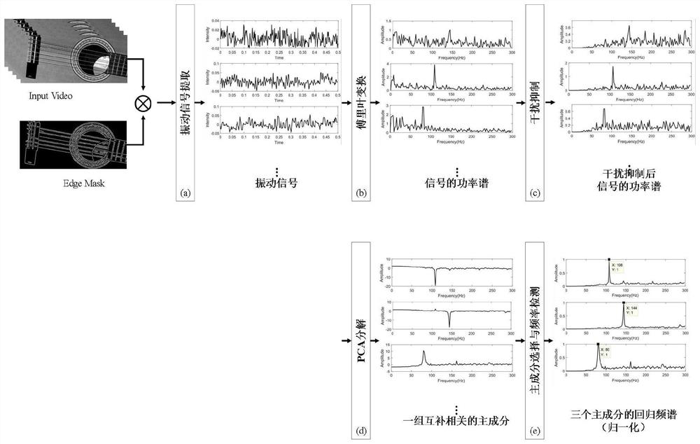
[0034] combine figure 1 , a multi-target micro-vibration frequency detection method based on Euler perspective of the present invention, comprising the following steps:

[0035] Step S1: collecting video data of vibrating objects in nature to extract tiny vibration signals;

[0036] In this step, according to an embodiment of the present invention, it is specifically:

[0037] 1a) Take a video of a vibrating object in a real scene with a Canon camera. The camera frame rate can be adjusted according to the actual situation. According to the Nyquist sampling theorem, the camera frame rate should be greater than 2 times the vibration frequency. The video capture time is 7 ...


PUM


Abstract

The invention discloses a multi-target micro-vibration frequency measurement method based on the Euler perspective. The method includes: collecting micro-vibration video data of an object in an actual scene, and using an edge mask image Edge Mask to extract N pixel points on the edge of the video image The brightness difference signal; use the Fourier transform to obtain the frequency spectrum of N groups of small vibration signals; extract the signal that interferes with the movement from the video data, and calculate the attenuation coefficient vector V(f q ), multiply the vector with the frequency spectrum of all tiny vibration signals; use PCA to decompose the frequency spectrum of all vibration signals to obtain a set of principal components arranged according to the size of the variance; use the method of maximum ratio of eigenvalues ​​to select a set of principal components Components, perform PCA regression on each principal component, obtain the mean spectrum, and normalize it; by detecting the frequency corresponding to the peak value in the normalized spectrum, the frequency of the vibration mode corresponding to the principal component can be obtained. The measuring method provided by the invention has the characteristics of fast measuring speed and high measuring precision.

Description

technical field [0001] The invention relates to the technical field of computer vision, in particular to a multi-target micro-vibration frequency detection method based on Euler's perspective in a real scene. Background technique [0002] Frequency information is an important basis for vibration analysis and is widely used in structural health inspection and quality inspection. People generally detect the vibration frequency by analyzing the vibration signal of the object. Traditional vibration signal detection methods include sensor-based contact vibration measurement and laser vibrometer-based non-contact vibration measurement, but these measurement methods are generally not suitable for simultaneous vibration measurement of multiple targets. [0003] The development of computer vision technology provides a new method for vibration signal detection. The visual measurement technology based on computer vision is based on modern optics and integrates modern science and tech...

Claims


Application Information

Patent Timeline
Patent Type & Authority Patents(China)
IPC IPC(8): G06K9/00G06K9/62G06V20/40G06V10/44G06V10/77
CPCG06V10/44G06F2218/10G06F2218/08G06F18/2135
Inventor 杨学志张龙沈晶宋正伟朱明扬臧宗迪周勇
Owner HEFEI UNIV OF TECH
Learn More