


Quick Research
Generate reliable direction feasibility study reports for your R&D in just a few steps.

Technical Q&A
Discover and master advanced knowledge NOW. Basics, ideas, possibilities, all at once.

Find Solutions
As an expert in R&D theories, this can generate solutions to your technical problems instantly.

Evaluate Feasibility
Analyze your overall solution with one click, know your potential R&D risks in advance.

Monitor Landscape
Get weekly tech updates, stay abreast of the latest tech innovations and key insights.
Anti-boiling sample thermogravimetric analysis device
A thermogravimetric analysis and anti-boiling technology, applied in the field of thermogravimetric analysis, can solve the problems of violent boiling, splashing, and inaccurate test results of the sample, and achieve the effect of timely temperature and accurate judgment
- Summary
- Abstract
- Description
- Claims
- Application Information
AI Technical Summary
Problems solved by technology
Method used
Image

Examples
Embodiment 1
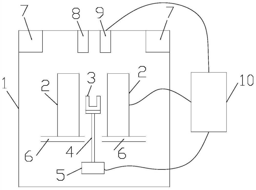
[0017] The invention provides an anti-boiling sample thermogravimetric analysis device. Such as figure 1 As shown, the anti-boiling sample thermogravimetric analysis device includes a heating assembly 2, a crucible 3, a mandrel 4, a balance 5, an air inlet 6, an exhaust assembly 7, a light source assembly 8, a detection assembly 9 and The control assembly 10 is arranged outside the chamber wall 1 . The heating assembly 2 forms a furnace, and the crucible 3 is placed in the furnace. The heating assembly 2 includes a resistance wire and a temperature detection assembly. The resistance wire is used to heat the crucible 3 and the samples in the crucible 3. The temperature detection assembly is used to detect the temperature in the furnace. The temperature detection assembly is a thermocouple. The crucible 3 is a porcelain crucible. The ejector rod 4 is arranged at the lower part of the crucible 3 to support the crucible 3 , and the balance 5 is located at the bottom of the ejec...
Embodiment 2
[0020] On the basis of Embodiment 1, the light source assembly 8 includes a continuous spectrum light source. The detection assembly 9 comprises a spectrometer. When the sample is about to boil, as the temperature increases, the particle size on the sample surface gradually increases, changing the corresponding resonance wavelength of the sample particles in the reflection spectrum. Therefore, the use of continuum light, spectrometer and light detector to detect the resonant wavelength of the particles in the reflection spectrum can more accurately determine whether the sample is boiling or will boil, and the detection is more accurate, so that the heating element 2 can be adjusted more precisely to prevent the sample from boiling.
Embodiment 3
[0022] On the basis of Embodiment 2, a transparent glass plate is provided on the upper side of the crucible 3 , and the transparent glass plate is suspended on the upper side of the crucible 3 through the cavity wall 1 . When the sample is about to boil, the particles evaporated from the sample are deposited on the transparent glass plate, which changes the reflection characteristics of the transparent glass plate. By detecting the reflectance spectrum of the transparent glass plate, it is determined whether the sample is boiling or about to boil. Because this embodiment measures the reflection spectrum after the particles are fixed on the transparent glass plate, it has the advantage of high detection accuracy.
PUM
 Abstract
Description
Claims
Application Information
 - R&D Engineer
- R&D Manager
- IP Professional
- Industry Leading Data Capabilities
- Powerful AI technology
- Patent DNA Extraction
Browse by: Latest US Patents, China's latest patents, Technical Efficacy Thesaurus, Application Domain, Technology Topic, Popular Technical Reports.
© 2024 PatSnap. All rights reserved.Legal|Privacy policy|Modern Slavery Act Transparency Statement|Sitemap|About US| Contact US: help@patsnap.com