Device for detecting flatness and coaxiality of steering wheel
A detection device and flatness technology, applied in the field of steering wheel flatness and coaxiality detection devices, can solve the problems of unstable operation of the device, uneven distribution of materials, errors in the detection of flatness by pressure sensors, and the like. Guarantee measurement accuracy, improve accuracy, and maintain the effect of stability
- Summary
- Abstract
- Description
- Claims
- Application Information
AI Technical Summary
Problems solved by technology
Method used
Image
Examples
Embodiment 1
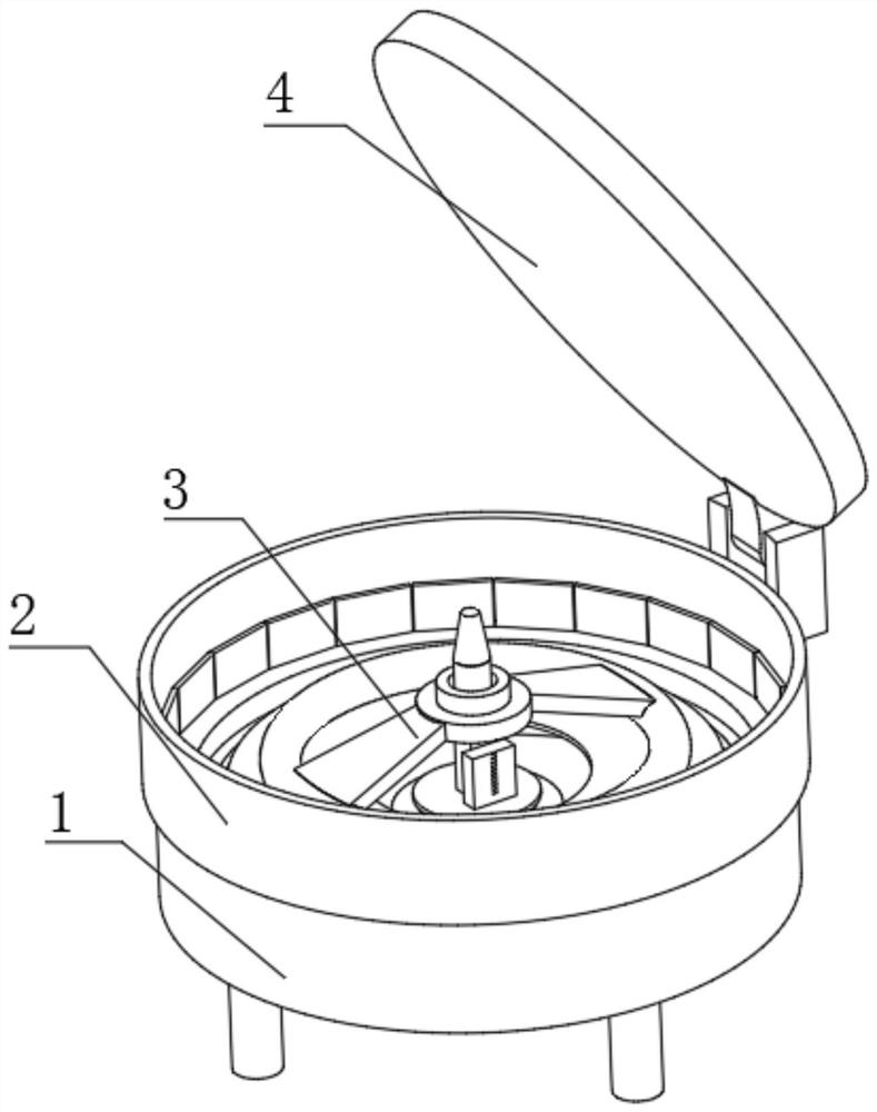
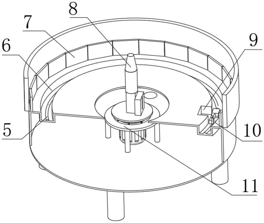
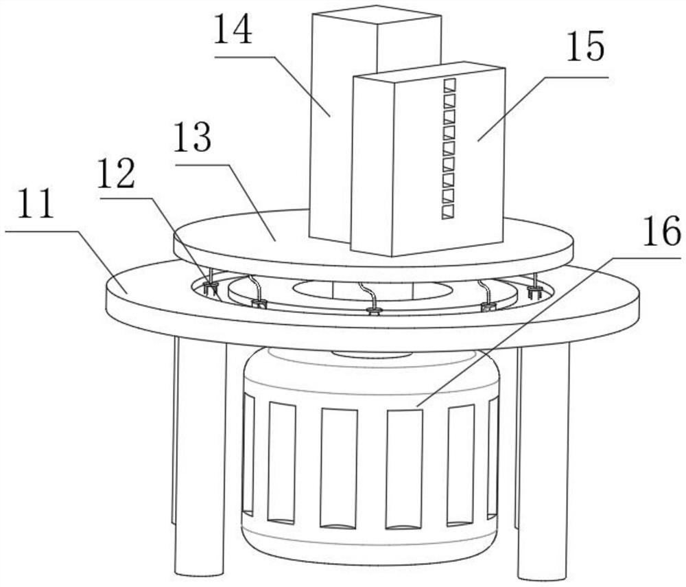
[0033] refer to Figure 1-6 , a detection device for steering wheel flatness and coaxiality, including a load-bearing box 1, the load-bearing box 1 is set to a cylindrical shape, and the top of the load-bearing box 1 is provided with a sliding groove 6, and the sliding groove 6 is arranged to be connected with the load-bearing box 1 The same circular center, the bottom inner wall of the sliding groove 6 is provided with an electric slide rail 5, and the inner wall of the electric slide rail 5 is slidably connected with a mounting block 10, and the top of the mounting block 10 has a circular groove, and the circular groove The inner wall of the bottom of the bottom is connected with the adjusting tube 23 by bolts, and the outer wall of the adjusting tube 23 has symmetrically distributed Pie-shaped grooves 24, the bottom inner wall of the adjusting tube 23 is welded with a spring 26, and the top of the spring 26 is welded with a spring plate 25, and The outer wall of the spring ...
Embodiment 2
[0037] refer to Figure 7 , a detection device for steering wheel flatness and coaxiality. Compared with Embodiment 1, this embodiment has a through hole at the center of the shade cover 4, and the inner wall of the through hole is connected with a fan 27 by bolts, and the through hole A shading screen is arranged at one end of the shading screen, and a plurality of ventilation holes are opened on the shading screen.
[0038] Working principle: When in use, turn the steering wheel 3 upside down and put it on the concentric shaft 8. Since the concentric shaft 8 is located on the center of the load-bearing box 1, when the steering wheel 3 is installed, it shares the same center of circle with the load-bearing box 1. On the steering wheel 3 After installation, the ring frame is in contact with the top of the load-bearing box 1. If the flatness of the steering wheel 3 is qualified, then the ring frame will fit the top of the load-bearing box 1, and the laser cannot pass through. W...
PUM
 Abstract
Description
Claims
Application Information
 - R&D
- Intellectual Property
- Life Sciences
- Materials
- Tech Scout
- Unparalleled Data Quality
- Higher Quality Content
- 60% Fewer Hallucinations
Browse by: Latest US Patents, China's latest patents, Technical Efficacy Thesaurus, Application Domain, Technology Topic, Popular Technical Reports.
© 2025 PatSnap. All rights reserved.Legal|Privacy policy|Modern Slavery Act Transparency Statement|Sitemap|About US| Contact US: help@patsnap.com


