Eureka AIR delivers breakthrough ideas for toughest innovation challenges, trusted by R&D personnel around the world.

Ultrahigh strength mining anchoring assembly and application

An ultra-high-strength, mining technology, used in mining equipment, bolt installation, earthwork drilling, etc., can solve the problems of poor bolt support and insufficient strength, and achieve good supporting effect, convenient installation, and improved performance. the effect of strength

Inactive Publication Date: 2020-11-27
CHINA UNIV OF MINING & TECH
View PDF6 Cites 0 Cited by
  • Summary
  • Abstract
  • Description
  • Claims
  • Application Information

AI Technical Summary

Problems solved by technology

[0005] In order to overcome the deficiencies in the prior art, the object of the present invention is to provide an ultra-high-strength mining anchor assembly and its application to solve the problems caused by the lack of strength of the anchor and the anchor tray in the existing bolt support. The problem of poor protection

Method used


Image

  • Ultrahigh strength mining anchoring assembly and application
  • Ultrahigh strength mining anchoring assembly and application
  • Ultrahigh strength mining anchoring assembly and application

Examples


Embodiment 1

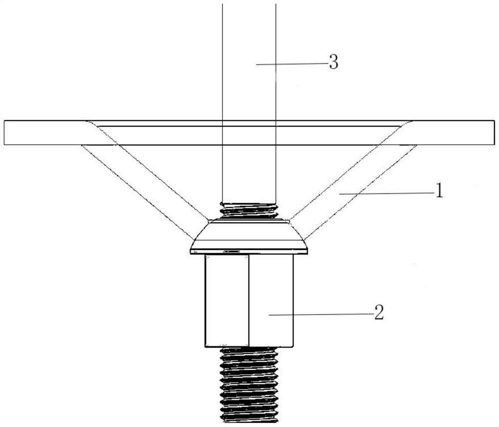
[0038] In this embodiment, the yield strength of the anchor rod 3 is 600Mpa to 800Mpa, and the section elongation is greater than 15%. According to the mass percentage, the material used for the anchor rod is composed of the following components: 0.2% carbon, 1% silicon, 3% manganese, 0.05% vanadium, 0.02% titanium, 0.01% niobium, 0.04% aluminum, and the rest are iron and trace impurity elements, The microstructure of the material is a low-carbon vanadium-niobium-titanium microalloyed bainite / martensite multiphase structure.

[0039] The material of the anchor tray 1 is Q235 steel, and the thickness of the tray is 9mm.

Embodiment 2

[0041] In this embodiment, the yield strength of the anchor rod 3 is 800Mpa to 1000Mpa, and the section elongation is greater than 15%. According to the mass percentage, the material used for the anchor rod is composed of the following components: 0.22% carbon, 0.5% silicon, 2% manganese, 0.09% vanadium, 0.01% titanium, 0.03% niobium, 0.02% aluminum, and the rest are iron and trace impurity elements, The microstructure of the material is a low-carbon vanadium-niobium-titanium microalloyed bainite / martensite multiphase structure.

[0042] The material of the anchor tray 1 is Q235 steel, and the thickness of the tray is 10mm.

Embodiment 3

[0044] In this embodiment, the yield strength of the anchor rod 3 is 1000Mpa to 1200Mpa, and the section elongation is greater than 15%. According to mass percentage, carbon 0.2%, silicon 0.6%, manganese 2.5%, vanadium 0.03%, titanium 0.04%, niobium 0.05%, aluminum 0.01%, the rest is iron and trace impurity elements, the microstructure of this material is low carbon vanadium niobium Titanium microalloyed bainite / martensite multiphase structure.

[0045] The material of the anchor tray 1 is Q345 steel, and the thickness of the tray is 10mm.


PUM

PropertyMeasurementUnit
yield strengthaaaaaaaaaa
angleaaaaaaaaaa
yield strengthaaaaaaaaaa

Abstract

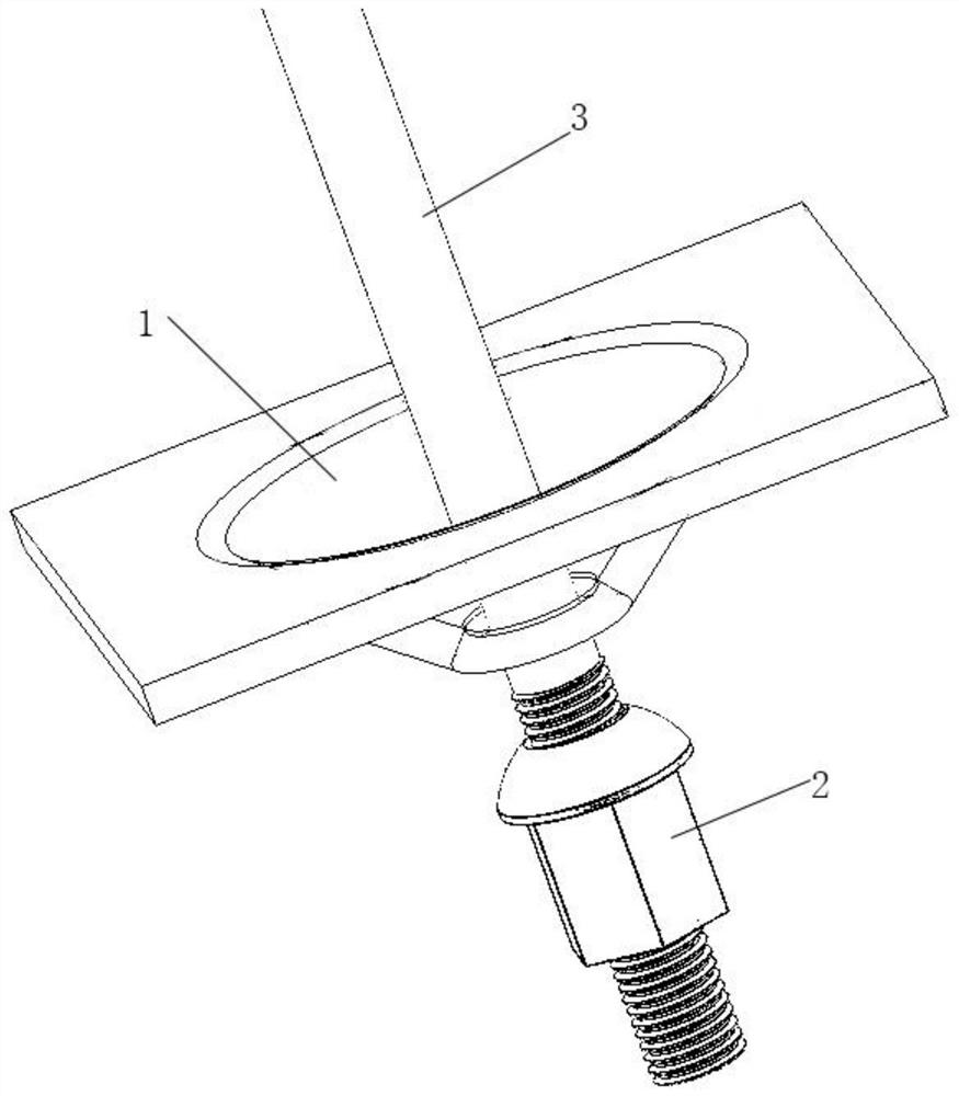
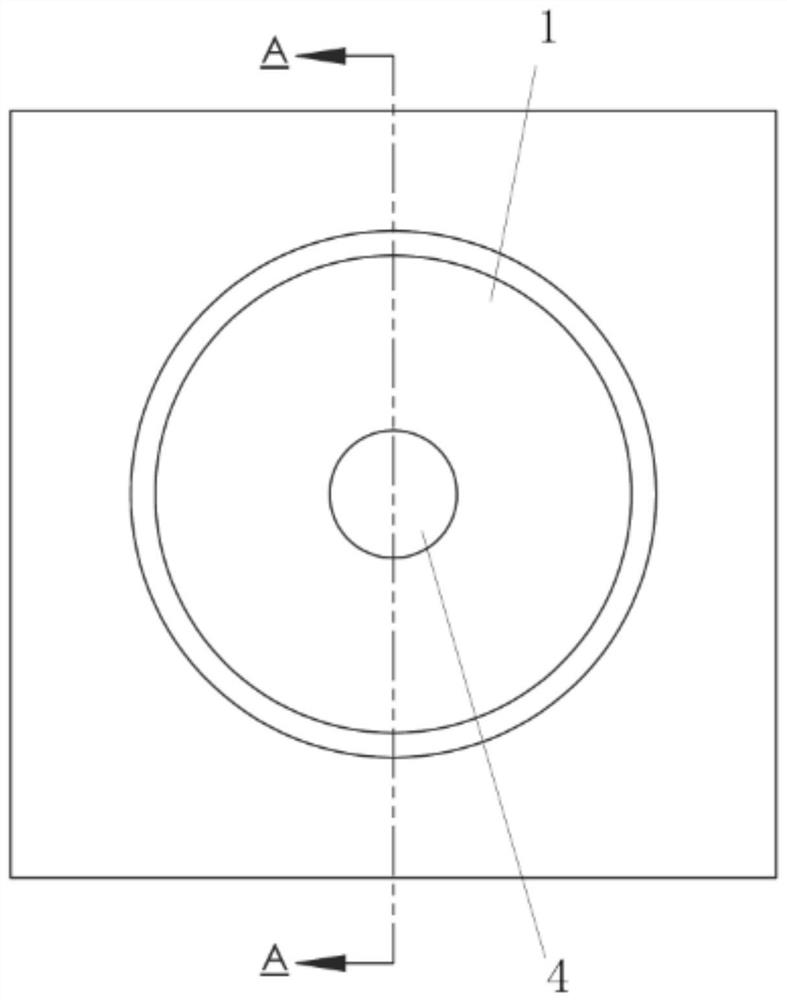
The invention discloses an ultrahigh strength mining anchoring assembly and application. The ultrahigh strength mining anchoring assembly comprises an anchor rod tray, a nut and an anchor rod. The anchor rod tray is circular truncated cone shaped, an anchor hole is formed in the bottom of the anchor rod tray, the anchor rod hole is circular truncated cone shaped, the anchor rod is inserted into the anchor rod hole and is fixed by the nut, and the end surface where the nut is in contact with the anchor rod hole is attached to the inner wall of the anchor rod hole. By means of integrated designof an anchoring assembly structure, a stress point is transferred to the nut, so that the integral strength of the anchor rod tray is improved greatly, the demand of the high strength anchor rod on the tray is met, the original anchoring strength is improved by 3 times integrally, the anchoring cost is lowered and the anchoring operation workload is reduced by 1 / 3.

Description

technical field [0001] The invention belongs to the technical field of safety support for coal mines and geotechnical engineering, and in particular relates to an ultra-high-strength mining anchor component and its application. Background technique [0002] With the development of our country's economy, people's requirements for the quality of life and the environment are constantly improving, and problems such as the shortage of land resources, the increase in energy demand, and the optimization and transformation of the natural environment have become increasingly prominent. Solving the above problems requires rational development of underground space, mining of mineral resources and environmental improvement, all of which involve safety support technology to ensure the stability of rock and soil. Anchor tray support is one of the commonly used methods in coal mine tunneling roadway support. Due to the influence of the roof surrounding rock type and its stress status, the ...

Claims


Application Information

Patent Timeline
Patent Type & Authority Applications(China)
IPC IPC(8): E21D21/00C22C38/02C22C38/04C22C38/06C22C38/12C22C38/14
CPCC21D2211/002C21D2211/008C22C38/02C22C38/04C22C38/06C22C38/12C22C38/14E21D21/0006E21D21/008
Inventor 陈正王振宇刘雨雨樊宇沈承金张平徐杰
Owner CHINA UNIV OF MINING & TECH
Why Eureka
Eureka Blog
Learn More