Eureka AIR delivers breakthrough ideas for toughest innovation challenges, trusted by R&D personnel around the world.

Constant-tension yarn feeder

A yarn feeder, constant tension technology, applied in the direction of conveying filamentous materials, thin material processing, transportation and packaging, etc., can solve the problem that the real-time adjustment and control of yarn tension detection cannot be effectively matched and realized, and the tension balance cannot be effectively realized. Controlling yarn feeding, poor sensitivity of tension sensor, etc., to achieve the effect of stable and balanced tension control yarn feeding, precise and efficient adjustment control, and high pressure detection accuracy

Pending Publication Date: 2020-11-27
QUANZHOU JINGZHUN MACHINERY
View PDF0 Cites 0 Cited by
  • Summary
  • Abstract
  • Description
  • Claims
  • Application Information

AI Technical Summary

Problems solved by technology

However, the tension sensor, motor and overfeeding mechanism need to be installed separately, which has low integration and takes up a lot of space; and the sensitivity of the tension sensor is poor, the tension measurement is inaccurate, and the yarn tension detection and the real-time adjustment control of the motor cannot be effectively matched. , so that the existing constant tension yarn feeder cannot effectively achieve tension balance control yarn feeding

Method used


Image

  • Constant-tension yarn feeder
  • Constant-tension yarn feeder
  • Constant-tension yarn feeder

Examples


Embodiment Construction

[0016] The present invention is further described in conjunction with accompanying drawing and specific embodiment now, wherein single-chip microcomputer control circuit, rotary encoder, first magnet, the motor that feeds yarn and feed super yarn, motor drive control circuit, display screen, tension setting circuit and power supply The circuits are all existing module parts, so only the innovative design of the present invention will be described in the following embodiments.

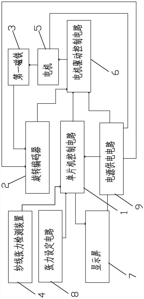
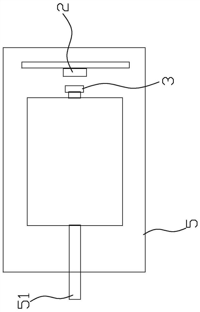
[0017] refer to Figure 1-Figure 7 , the preferred constant tension yarn feeder of the present invention includes a single-chip microcomputer control circuit 1, a rotary encoder 2, a first magnet 3, a motor 5 for yarn feeding and super yarn feeding, a motor drive control circuit 6, a display screen 7, and a tension setting device. Fixed circuit 8, power supply circuit 9 and yarn tension detection device 4, described single-chip microcomputer control circuit 1 is made of single-chip microcomputer STM32F1...


PUM


Abstract

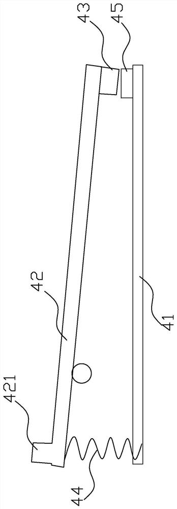
The invention relates to the technical field of textile machinery, and provides a constant-tension yarn feeder. The constant-tension yarn feeder comprises a single-chip microcomputer control circuit,a rotary encoder, a first magnet, a motor for feeding super yarn, a motor drive control circuit, a display screen, a tension setting circuit, a power supply circuit and a yarn tension detection device, the yarn tension detection device comprises a base, a lever arranged on the base, a second magnet, a spring and a Hall sensor, the Hall sensor detects yarn tension compression pressure of yarn feeding in real time and sends the yarn tension compression pressure to the single-chip microcomputer control circuit, the rotary encoder divides a motor shaft of the motor into 4096 parts after rotating for one circle and 360 degrees, accurately identifies the rotation angle of the motor shaft of the motor and the real-time position of a motor rotor by sensing the first magnet, and sends the rotationangle and the real-time position to the motor driving control circuit; the single-chip microcomputer control circuit controls the speed of the motor through the motor drive control circuit to adjust the tension of the yarn. The constant-tension yarn feeder solves the problem that an existing constant-tension yarn feeder cannot effectively achieve tension balance control yarn feeding.

Description

technical field [0001] The invention relates to the technical field of textile machinery, in particular to a constant tension yarn feeder. Background technique [0002] In textile production, as we all know, the yarn feeder is an important component mechanism in the yarn production equipment, which is used to transport the yarn. However, the yarn feeder in the prior art cannot adjust the conveying speed according to the tension of the yarn in real time, thus affecting the yarn forming quality. There are also some advanced yarn production equipment on the market that use coordinated control of tension sensors, motors and overfeeding mechanisms to adjust yarn tension. However, the tension sensor, motor and overfeeding mechanism need to be installed separately, which has low integration and takes up a lot of space; and the sensitivity of the tension sensor is poor, the tension measurement is inaccurate, and the yarn tension detection and the real-time adjustment control of the...

Claims


Application Information

Patent Timeline
Patent Type & Authority Applications(China)
IPC IPC(8): B65H59/10B65H59/40
CPCB65H59/10B65H59/40
Inventor 黄毅杨骆汉城林庆龙
Owner QUANZHOU JINGZHUN MACHINERY
Why Eureka
Eureka Blog
Learn More