
Toggling type cutting and feeding device

A cutting and punching technology, which is applied in the field of toggle cutting and feeding devices, can solve the problems of inaccurate positioning of feeding and feeding back, so as to achieve tight integration of feeding and reduce incomplete cutting. , Improve the effect of cutting precision and feeding efficiency

Active Publication Date: 2020-11-27
SUZHOU RS TECH
View PDF10 Cites 1 Cited by
  • Summary
  • Abstract
  • Description
  • Claims
  • Application Information

AI Technical Summary

Problems solved by technology

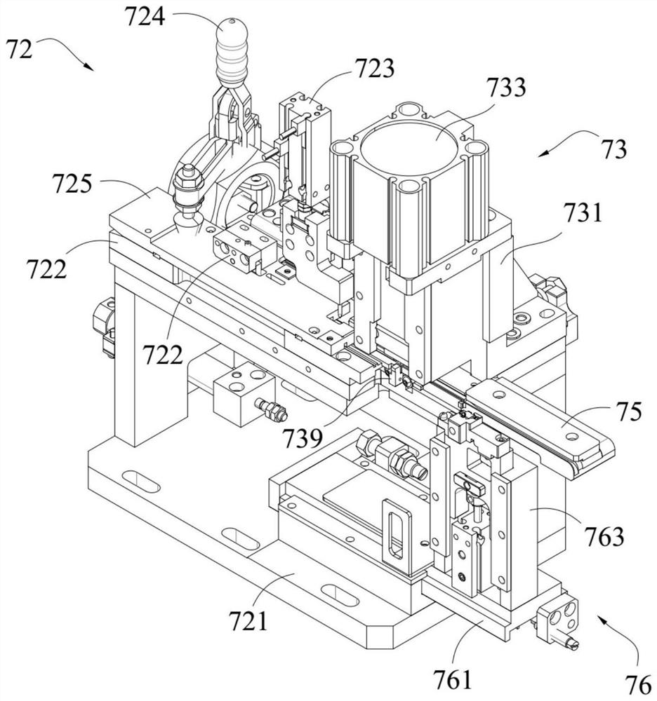
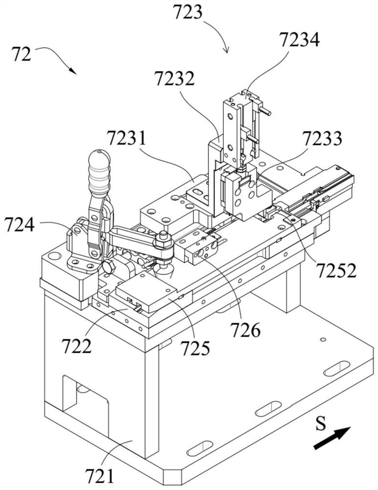
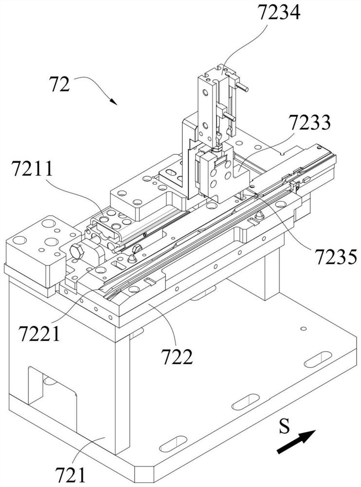
[0006] Aiming at the deficiencies in the prior art, the main purpose of the present invention is to provide a dial-type cutting and feeding device, which uses a dial-type feeding structure to solve the problem of intermittent feeding in traditional double-disc feeding. In the process, problems such as inaccurate positioning of the feeding material, backtracking of the feeding material, tearing of the material tape, and curling of the material tape are likely to occur, which improves the feeding efficiency and accuracy of the material, and finally improves the production efficiency. Through the punching and cutting mechanism and the The cooperation of the material cutting mechanism realizes that after the workpiece is cut from the material belt, it can be stably held by the material cutting mechanism located below the punching and cutting mechanism and transferred to the transfer station for the loading manipulator to grab. The close and efficient cooperation of cutting-transfer-loading integration improves the cutting accuracy and feeding efficiency of the workpiece, and finally further improves the production efficiency

Method used


Image

  • Toggling type cutting and feeding device
  • Toggling type cutting and feeding device
  • Toggling type cutting and feeding device

Examples


Embodiment Construction

[0064] The technical solutions in the embodiments of the present invention will be clearly and completely described below in conjunction with the accompanying drawings in the embodiments of the present invention. Obviously, the described embodiments are only part of the embodiments of the present invention, not all of them. Based on the implementation methods in the present invention, all other embodiments obtained by persons of ordinary skill in the art without making creative efforts belong to the protection scope of the present invention.

[0065] In the drawings, the shapes and dimensions may be exaggerated for clarity, and the same reference numerals will be used throughout to designate the same or like parts.

[0066] Unless otherwise defined, the technical terms or scientific terms used herein shall have the usual meanings understood by those skilled in the art to which the present invention belongs. "First", "second" and similar words used in the patent application spe...


PUM


Abstract

The invention discloses a toggling type cutting and feeding device comprising a toggling feeding mechanism, a blanking and cutting mechanism, a cut material bearing mechanism and a toggling drive; thetoggling feeding mechanism comprises a fixedly-arranged feeding rack and a toggling assembly arranged on the feeding mechanism; the blanking and cutting mechanism is arranged on the feeding rack andlocated on the downstream of the toggling assembly; the cut material bearing mechanism is arranged on the feeding rack and located below the blanking and cutting mechanism; a power output end of the toggling drive is in transmission connection with the toggling assembly, wherein the feeding rack is provided with a material belt guide plate, and the material belt guide plate is provided with a material belt conveying guide rail extending in the straight line direction; the toggling assembly is connected with the feeding rack in a sliding mode; and a blanking bearing platform located on the downstream of the material belt conveying guide rail is fixedly arranged on the feeding rack. According to the toggling type cutting and feeding device, a toggling type feeding structure is adopted, and the blanking and cutting mechanism and the cut material bearing mechanism cooperate with each other, so that the cutting precision and the feeding efficiency of workpieces are improved, and finally theproduction efficiency is improved.

Description

technical field [0001] The invention relates to the field of electric vehicles, in particular to a toggle type cutting and feeding device. Background technique [0002] In the field of non-standard automation, it is well known to use feeding devices with different structural forms to realize efficient feeding of material strips. In the process of researching and realizing efficient loading of workpieces, the inventors found that there are at least the following problems in the loading device in the prior art: [0003] First of all, most of the existing coiled material belts use the double-disc feeding method of discharging from the discharging tray and receiving from the receiving tray. This method of feeding is suitable for continuous and uninterrupted feeding. For intermittent feeding, especially intermittent In terms of feeding requirements with short time intervals, the double-disk feeding process will easily lead to inaccurate feeding positioning, feeding back, tearing...

Claims


Application Information

Patent Timeline
Patent Type & Authority Applications(China)
IPC IPC(8): B65H35/06B65H5/22
CPCB65H35/06B65H5/22
Inventor 缪磊冯小平肖夕全袁文卿王坤
Owner SUZHOU RS TECH
Learn More