
Disposable dilator for gynecologic examination

A gynecological examination, one-time technology, applied in the field of medical devices, can solve the problems of exacerbation, cross-infection, patient discomfort, etc., and achieve the effect of reducing pain, preventing repeated use, and avoiding the infection of diseases

Inactive Publication Date: 2020-11-27
李园媛
View PDF0 Cites 2 Cited by
  • Summary
  • Abstract
  • Description
  • Claims
  • Application Information

AI Technical Summary

Problems solved by technology

[0003] However, the existing vaginal dilator is a very thin duckbill clip, which is divided into upper and lower expansion wings, which can only expand the vagina up and down when opened, and the expansion wings are flat and have a small radian, not only the expansion effect is not good , and it will bring discomfort to the patient, which will also hinder the development of medical operations. Secondly, the observation port of the vaginal dilator is always open. However, it is brought into the patient's vagina, causing the patient's condition to worsen. The conventional product can return to its original position after use. If it is reused, it will cause the patient's infectious disease or cross-infection. Therefore, those skilled in the art provide a Disposable dilator for gynecological examination to solve the problems raised in the background art above

Method used


Image

  • Disposable dilator for gynecologic examination
  • Disposable dilator for gynecologic examination
  • Disposable dilator for gynecologic examination

Examples


Embodiment Construction

[0022] The following will clearly and completely describe the technical solutions in the embodiments of the present invention with reference to the accompanying drawings in the embodiments of the present invention. Obviously, the described embodiments are only some, not all, embodiments of the present invention. Based on the embodiments of the present invention, all other embodiments obtained by persons of ordinary skill in the art without making creative efforts belong to the protection scope of the present invention.

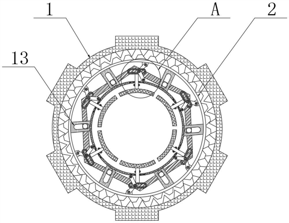
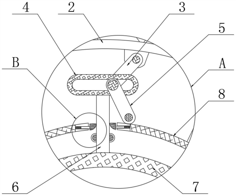
[0023] see Figure 1-7 , a disposable dilator for gynecological examination, comprising an external toothed ring 1, the inner wall of the external toothed ring 1 is meshed with an internal toothed ring 2, the outer surface of the external toothed ring 1 is fixedly connected with a raised block 19, the external toothed ring The inner wall of 1 is fixedly connected with a rack 20, the width of the outer gear ring 1 is smaller than the width of the inner gear rin...


PUM


Abstract

The invention relates to the technical field of medical instruments, in particular to a disposable dilator for gynecologic examination. A first pull rod is movably connected to the inner wall of an inner gear ring; an annular plate is movably connected to one end of the first pull rod; a second pull rod is movably connected to the surface, opposite to the first pull rod, of the outer surface of the annular plate; a fixed annular plate is fixedly connected to the other end of a short plate; a third pull rod is fixedly connected to the bottom end of the annular plate in a manner of movably penetrating through the lower portion of the fixed annular plate; a clamping groove is formed in the short plate; a movable shaft is movably connected to the interior of the clamping groove; and a polygonal groove is formed in the position, located on the rear side of the short plate, of the outer wall of an inner gear ring. Under the support of the second pull rod, the first pull rod drives the annular plate and the third pull rod at the bottom of the annular plate to move towards the outer side of the fixed annular plate, so that expansion wings expand outwards to open the vagina; and due to thefact that the expansion wings are six smooth arc-shaped structures, the pain of a patient is relieved during vagina expansion.

Description

technical field [0001] The invention relates to the technical field of medical devices, in particular to a disposable dilator for gynecological examination. Background technique [0002] When women undergo gynecological examination or surgical treatment, a commonly used instrument is a vaginal dilator, which is a vaginal dilator. The product requires high transparency and no burrs. It is used in cervical conization, cervical LEEP conization, During cervical biopsy and other operations that require transvaginal operations, it is necessary to use a vaginal dilator to fully dilate the vagina so that doctors can perform various medical operations on the cervix or uterine cavity. [0003] However, the existing vaginal dilator is a very thin duckbill clip, which is divided into upper and lower expansion wings, which can only expand the vagina up and down when opened, and the expansion wings are flat and have a small radian, not only the expansion effect is not good , and it will ...

Claims


Application Information

Patent Timeline
IPC IPC(8): A61B1/32
CPCA61B1/32
Inventor 李园媛
Owner 李园媛
Learn More