
System and method for detecting pulses in received signal in streaming manner

A signal and pulse technology, applied in the field of radar pulse detection, which can solve problems such as limiting the detection range of the receiver and high signal-to-noise ratio

Pending Publication Date: 2020-11-24
THE BOEING CO
View PDF0 Cites 1 Cited by
  • Summary
  • Abstract
  • Description
  • Claims
  • Application Information

AI Technical Summary

Problems solved by technology

This approach therefore limits the processing of pulses to those with a relatively high signal-to-noise ratio (pulses that are easily distinguished from noise)
This in turn limits the detection range of any receiver using thresholding techniques (unless the transmitter signal power is increased)

Method used


Image

  • System and method for detecting pulses in received signal in streaming manner
  • System and method for detecting pulses in received signal in streaming manner
  • System and method for detecting pulses in received signal in streaming manner

Examples


Embodiment approach

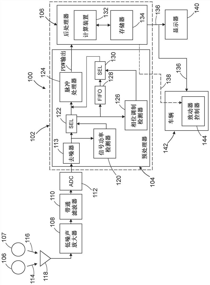
[0084] Item 1. A method for streaming detection of pulses in a received signal comprising:

[0085] (a) sampling the received signal to produce samples in digital format;

[0086] (b) estimating a corresponding signal power of the received signal for each sample;

[0087] (c) determining that the signal power estimated in step (b) is less than a signal power threshold;

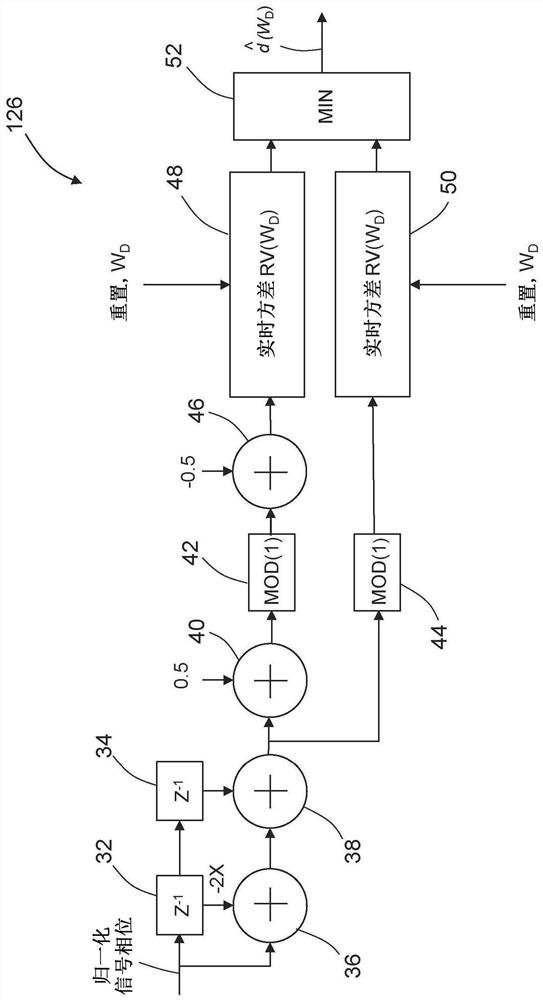
[0088] (d) after step (c), estimating a corresponding second order difference in phase of a plurality of samples within the window;

[0089] (e) determining that the second order difference estimated in step (d) is less than the phase difference threshold; and

[0090] (f) Processing the samples within the window to generate an information vector comprising a corresponding data set of parameter values ​​for pulses in the received signal.

[0091] Item 2. The method of item 1, further comprising storing the samples within the window in a first-in-first-out buffer during step (c) and before step (f).

[0092...


PUM


Abstract

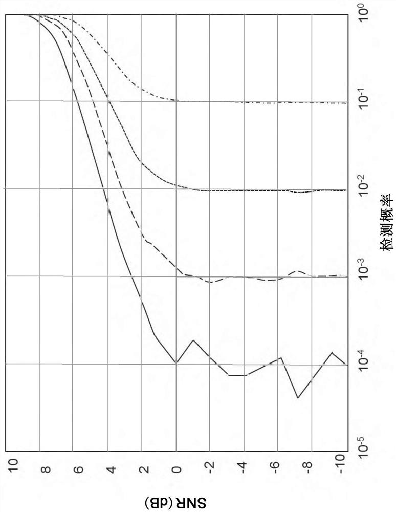
The disclosure relates to a system and a method for detecting pulses in received signals in a streaming manner. A threshold detection method is fused with a double-difference phase modulation detection method to provide a higher-performance method of pulse detection for any digital receiver. The first pulse detection technique uses a signal power threshold. When the square of the magnitude of a pulse crosses the signal power threshold, the beginning of a pulse is declared and pulse processing starts. The second pulse detection technique is model based and uses a windowed detector that crossesa phase difference threshold when the pulse has consistent second-order (in general d-th order) difference phase values within the window. The first technique has low latency and is independent of pulse width, but only operates well at SNR values greater than 15 dB. The second technique has higher latency and requires a minimum pulse width, but operates at lower (approximately 0 dB) SNR values.

Description

technical field [0001] The techniques disclosed herein generally relate to radar pulse detection. In particular, it relates to radar pulse detection using digital radar receivers. Background technique [0002] A receiver system is any system configured to receive energy waves and process these energy waves to identify desired information carried in the energy waves. As used herein, an "energy wave" is a disturbance that propagates through at least one medium while carrying energy. For example, energy waves may include electromagnetic waves, radio waves, microwaves, sound waves, or ultrasound waves. [0003] Typically, a receiver system includes a transducer and a receiver. A transducer may be any device configured to convert one type of energy into another type of energy. Transducers used in receiver systems are typically configured to receive energy waves and convert these energy waves into electrical signals. An antenna is an example of a transducer. The receiver pro...

Claims


Application Information

Patent Timeline
Patent Type & Authority Applications(China)
IPC IPC(8): G01S7/02G01S7/32
CPCG01S7/021G01S7/32G01S7/2921G01S7/2922G01S13/931G01S3/043G01S7/2926G01S7/285H04L27/22
Inventor 加里·A·雷
Owner THE BOEING CO
Learn More