Plasma display unit

A display device and plasma technology, which can be used in identification devices, cold cathode tubes, instruments, etc., and can solve problems such as the expansion of the bright area.

Inactive Publication Date: 2003-08-27
AU OPTRONICS CORP
View PDF0 Cites 0 Cited by
  • Summary
  • Abstract
  • Description
  • Claims
  • Application Information

AI Technical Summary

Problems solved by technology

However, no matter which method is used, although it can improve the contrast, it cannot expand the range of bright areas for a fixed pixel size.

Method used


Image

  • Plasma display unit
  • Plasma display unit
  • Plasma display unit

Examples


Embodiment Construction

[0021] When manufacturing the plasma display device disclosed in the present invention, similar processes and manufacturing parameters to those of known plasma display devices can be used without greatly changing the manufacturing steps. Therefore, ordinary manufacturers of plasma display devices can implement the present invention by using existing equipment without adding additional costs.

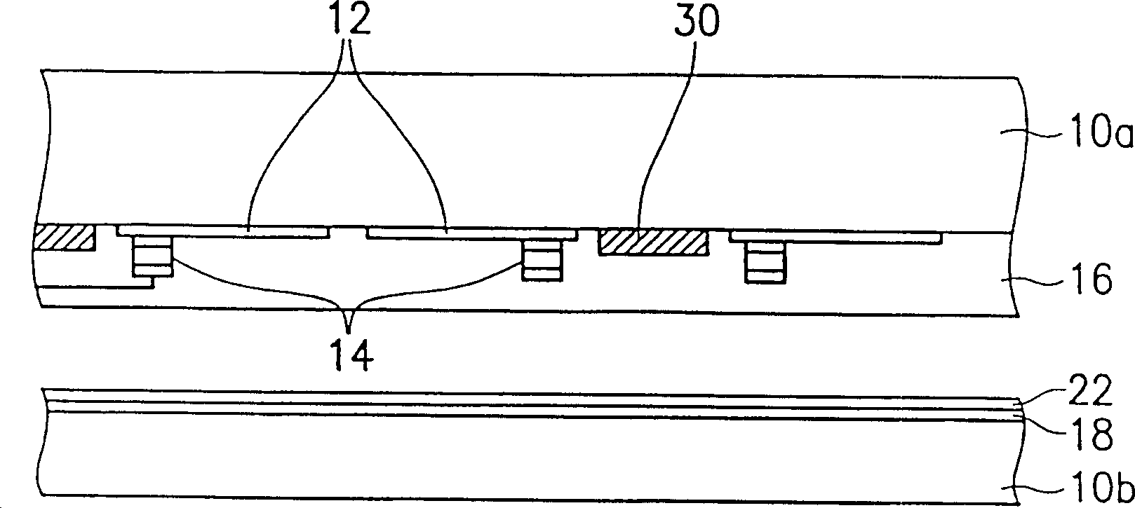
[0022] According to the first embodiment of the present invention, in order to improve the adhesion of the auxiliary electrode, in the step of etching the transparent electrode, the position where the auxiliary electrode is formed on the transparent electrode can be etched simultaneously. In this way, after the auxiliary electrode is formed, due to the auxiliary electrode The electrodes are in direct contact with the substrate, so they have good adhesion.

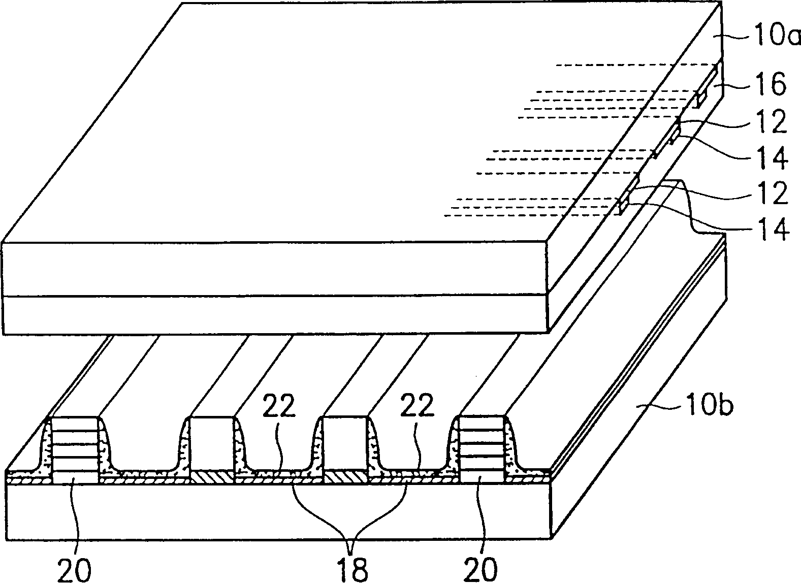
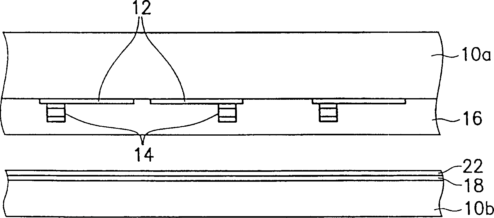
[0023] refer to Figure 4 , in this embodiment, the plasma display device includes: a pair of parallel and opposite substrates, inc...


PUM


Abstract

The plasma display unit has enlarged bright area in unchanged pixel size and raised adhesion of supplementary electrode. The plasma display unit has altered position to form the supplementary electrode, so that the supplementary electrode contacts not only to transparent electrode but also to the base and has improved adhesion. Furthermore, the position of the supplementary electrode is shifted towards outside of the transparent electrode to increase the bright area of the transparent electrode.

Description

technical field [0001] The invention relates to a plasma display device, in particular to a plasma display device with a larger main bright area. Background technique [0002] The front plate electrode of a general plasma display device (Plasma Display Panel, referred to as PDP) is made of known semiconductor manufacturing technology, and its light emitting mode can be divided into two types: transmissive type and reflective type, among which the so-called transmissive type The PDP means that the fluorescent material is formed on the front plate; while the reflective PDP means that the fluorescent material is formed on the rear plate. The current research is towards the development of reflective PDP. [0003] The front plate electrode can be divided into two types, one is a transparent electrode, which is generally made of ITO material, and the other is an auxiliary electrode, which is an opaque material, and is generally made of a triad of Cr / Cu / Cr or Cr / Al / Cr. layer stru...

Claims


Application Information

Patent Timeline
IPC IPC(8): G09F9/313H01J17/49
Inventor 苏耀庆宋文发林义哲
Owner AU OPTRONICS CORP
Why Eureka
Try Eureka