
Portable glass can capping machine

A glass jar and capping machine technology, applied to screw caps and other directions, can solve the problems of increasing the workload of operators, the inability of the cap and the bottle body to be in a parallel state, and the shaking of the cap, so as to improve the sealing effect of capping. Effect

Inactive Publication Date: 2020-11-24
邱鹏鸿
View PDF7 Cites 1 Cited by
  • Summary
  • Abstract
  • Description
  • Claims
  • Application Information

AI Technical Summary

Problems solved by technology

[0004] Aiming at the deficiencies in the prior art, the purpose of the present invention is to provide a portable glass jar capping machine to solve the problem that when capping a glass jar, the bottle cap is usually clamped with claws, and the cap is clamped by the claws. Tighten at the middle position of the outer ring of the bottle cap. During the tightening process, due to the friction between the inner ring of the claw and the bottle cap, there will be wear marks on the bottle cap. The secondary replacement of the worn bottle cap will increase the workload of the operator and bring unnecessary troubles to the operator, and when the claws grab the bottle cap, the bottle cap will shake, making the bottle cap and the bottle body Unable to be in a parallel state, resulting in that the bottle cap cannot completely match the bottle body when screwing the cap, resulting in incomplete capping of the bottle body, reducing the sealing effect of the glass jar and the quality of the capping quality of the glass jar

Method used


Image

  • Portable glass can capping machine
  • Portable glass can capping machine
  • Portable glass can capping machine

Examples


Embodiment 1

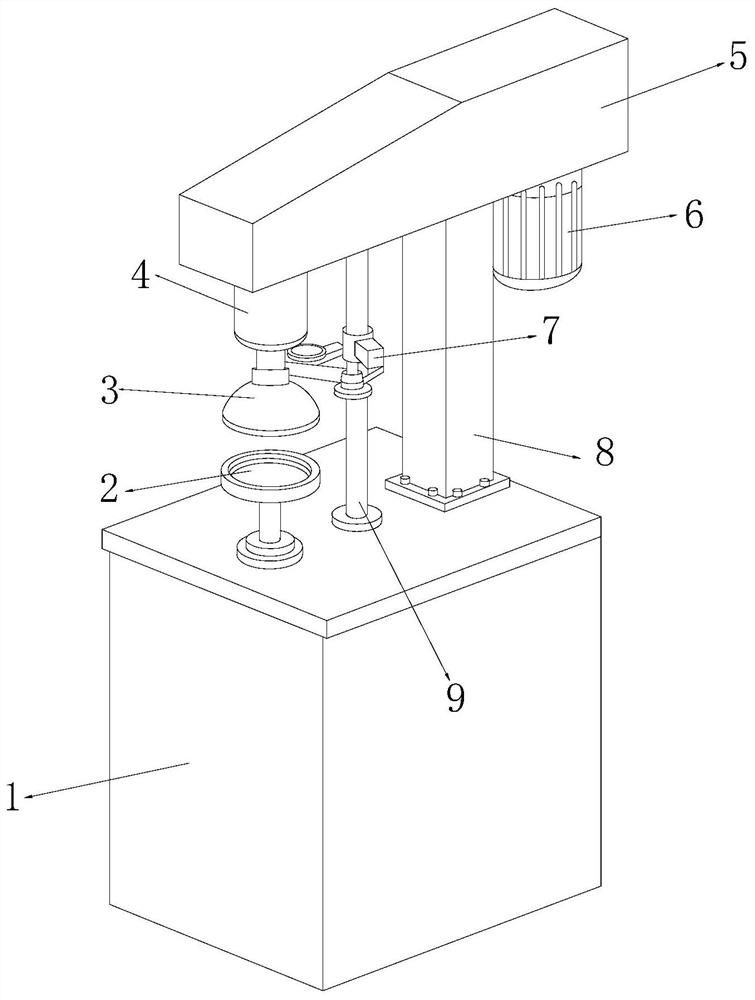
[0032] see figure 1 , the present invention provides a technical solution: a portable glass jar capping machine, the structure of which includes a body 1, a placement seat 2, a protection device 3, a rotating head 4, a mounting part 5, a motor 6, a positioning fastener 7, and a support column 8. Connecting rod 9. Placement seat 2, support column 8, and connecting rod 9 are installed on the top of the body 1. Placement seat 2, support column 8 and connecting rod 9 form the same straight line with each other, and the placement seat 2 is vertically fitted On the body 1, the support column 8 and the connecting rod 9 are fixed on the body 1 through screw locking, the support column 8 and the connecting rod 9 are connected through the mounting part 5, and the bottom end of the mounting part 5 is provided with a motor 6. The motor 6 is electrically connected to the inside of the body 1 through wires, the motor 6 and the rotary head 4 are arranged on the same module, the two sides of...

Embodiment 2

[0042] see figure 1 , the present invention provides a technical solution: a portable glass jar capping machine, the structure of which includes a body 1, a placement seat 2, a protection device 3, a rotating head 4, a mounting part 5, a motor 6, a positioning fastener 7, and a support column 8. Connecting rod 9. Placement seat 2, support column 8, and connecting rod 9 are installed on the top of the body 1. Placement seat 2, support column 8 and connecting rod 9 form the same straight line with each other, and the placement seat 2 is vertically fitted On the body 1, the support column 8 and the connecting rod 9 are fixed on the body 1 through screw locking, the support column 8 and the connecting rod 9 are connected through the mounting part 5, and the bottom end of the mounting part 5 is provided with a motor 6. The motor 6 is electrically connected to the inside of the body 1 through wires, the motor 6 and the rotary head 4 are arranged on the same module, the two sides of...


PUM


Abstract

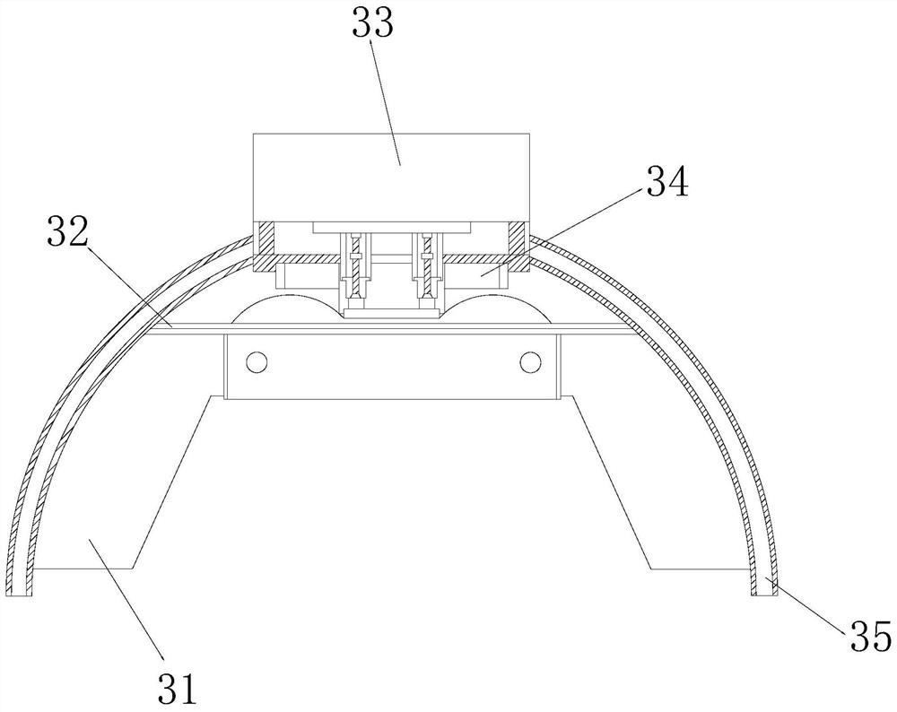
The invention discloses a portable glass can capping machine. The portable glass can capping machine structurally comprises a machine body, a placing seat, a protection device, a rotating head, a mounting piece, a motor, a positioning fastener, a supporting column and a connecting rod. When the portable glass can capping machine is used after being improved, a bottle cap is stably clamped on the inner ring of an air bag, when the rotating head rotates, friction force is generated between the air bag and the bottle cap, the bottle cap does not slide when being screwed, the air bag is made of aflexible rubber material, the outer wall of the bottle cap can be protected, and the phenomenon of grinding marks is avoided; the bottle cap is placed on a direction adjusting disc, so that the bottlecap and a bottle body are ensured to be in a parallel state, the bottle cap is positioned on a frame body by using two clamping plates, air in a guide-out cavity is adsorbed by using a nozzle, the nozzle sprays compressed air, the adsorbed air is sucked to a ventilation ring groove through an air suction pipe, and as a result, the pressure in a vacuum cavity is reduced to be below the atmosphericpressure, a certain vacuum degree is formed, the bottle cap can be matched with a can body for stable capping, and the capping and sealing effect of the glass can is improved.

Description

technical field [0001] The invention relates to the field of glass jar capping machinery, in particular to a portable glass jar capping machine. Background technique [0002] The capping machine is a machine for mechanized capping. It refers to capping and capping various plastic barrels and glass bottles. Capping has good moisture-proof, mildew-proof, and anti-counterfeiting functions, and it can prolong the storage period of items and reduce work. Personnel manually carry out the capping process and ensure the capping is tight. This machine is a multi-functional model. It can be used for oral liquid anti-theft caps, large infusion aluminum caps and liquor caps by changing different accessories. It can also be used for three Screw caps, four-screw caps and screw caps of various plastic caps can also be used to press crown caps such as soda and beer. When capping glass jars, what needs to be improved: [0003] When capping a glass jar, the bottle cap is usually clamped wit...

Claims


Application Information

Patent Timeline
Patent Type & Authority Applications(China)
IPC IPC(8): B67B3/20
CPCB67B3/20
Inventor 邱鹏鸿
Owner 邱鹏鸿
Learn More