
A vacuum-driven radial automatic positioning device

A positioning device and automatic positioning technology, used in positioning devices, manufacturing tools, metal processing machinery parts, etc., can solve the problems of affecting processing efficiency, large deviation of knocking amount, time-consuming and laborious, etc., to achieve convenient operation and reliable positioning. 、Reliable and accurate positioning effect

Active Publication Date: 2021-08-27
INST OF CHEM MATERIAL CHINA ACADEMY OF ENG PHYSICS
View PDF0 Cites 0 Cited by
  • Summary
  • Abstract
  • Description
  • Claims
  • Application Information

AI Technical Summary

Problems solved by technology

[0002] In the prior art, the CNC vertical lathe adopts vacuum suction cups for clamping when processing a certain product. Each clamping needs to manually install the dial indicator and the dial indicator frame for radial jump alignment. The sub-meter is shaken by the hand wheel to press a certain value on the product surface, and then by rotating the main shaft of the machine tool, tap the high point of the product with a tool or hand, and repeat it several times until the center of rotation of the product is consistent with the center of rotation of the machine tool. Through this method It is time-consuming and laborious to find the processed products to meet the requirements of the processing technology, which seriously affects the processing efficiency
[0003] Every time you install the dial indicator stand, you need to pay special attention to whether the dial indicator passes the center of rotation, so as to prevent the dial indicator from deviating from the center of rotation, resulting in a large deviation in the amount of each knock, which increases the difficulty of alignment
There is still the phenomenon of forgetting to remove the dial indicator frame after the alignment is completed by using the method of installing the dial indicator frame, which brings certain safety risks to the processing.

Method used


Image

  • A vacuum-driven radial automatic positioning device
  • A vacuum-driven radial automatic positioning device

Examples


Embodiment 1

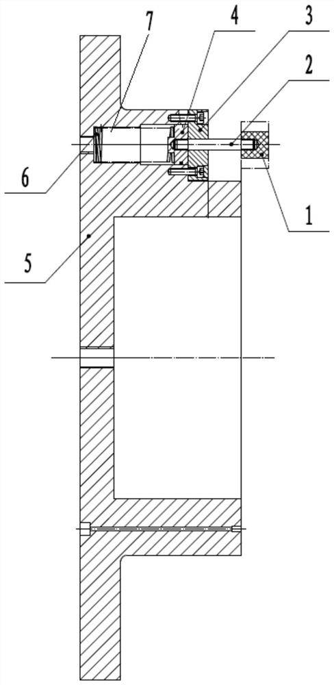
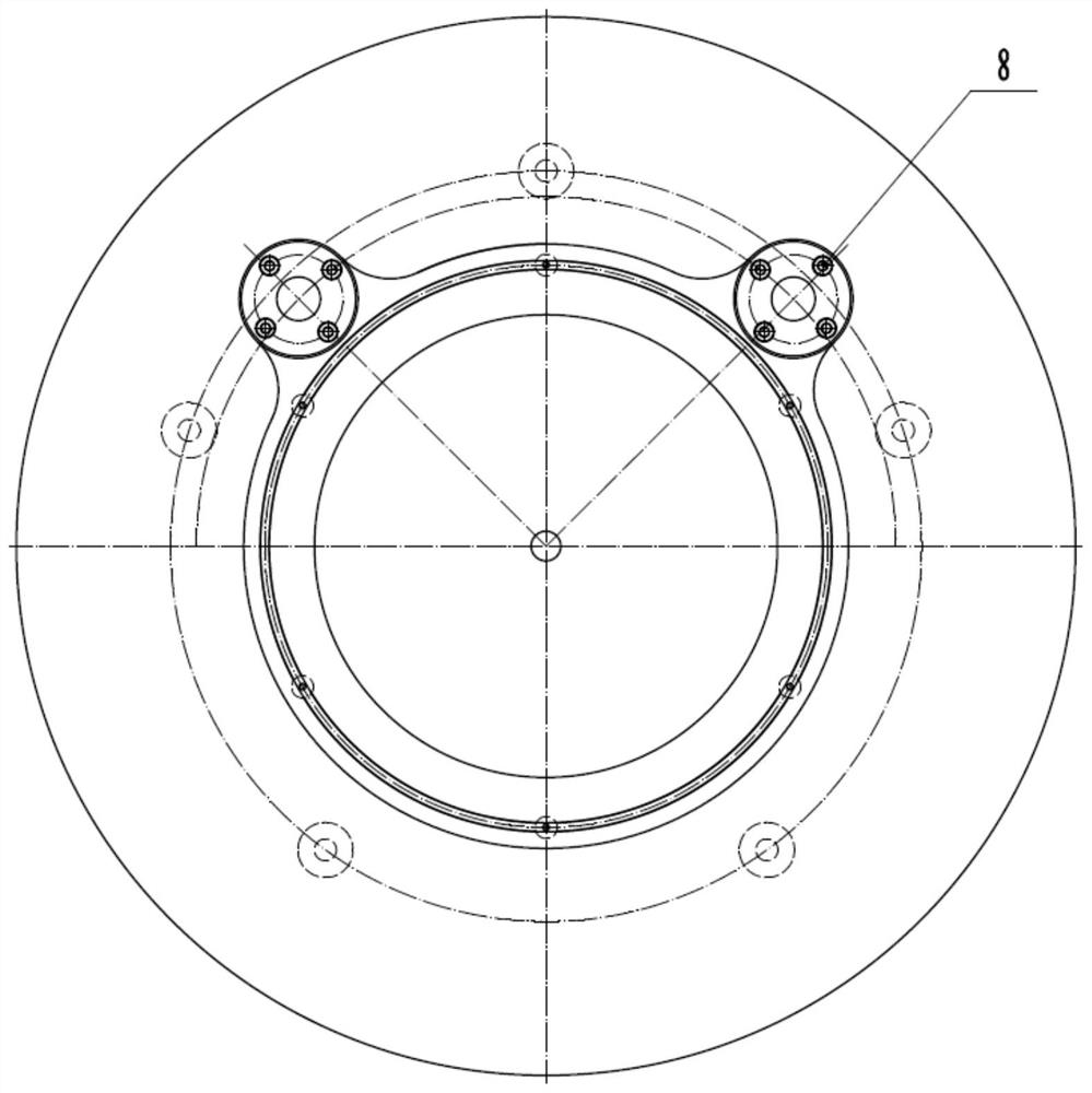
[0023] Such as figure 1 and 2 As shown, a vacuum-driven radial automatic positioning device includes a vacuum chuck 5 for absorbing workpieces. Two positioning devices 8 are provided on the vacuum chuck 5, and the two positioning devices 8 are arranged along the axis of the vacuum chuck 5. Slidingly connected to the vacuum chuck 5, the two positioning devices 8 are arranged on a concentric circle with the axis of the vacuum chuck 5 as the center, and the connecting line between the two positioning devices 8 does not pass through the center of the concentric circle.

[0024] The present invention designs a set of vacuum-driven radial automatic positioning devices aimed at the problems in the background technology. This device adopts a vacuum-driven mode to realize the radial positioning device 8, which can automatically lift according to actual needs. When positioning is required, the positioning device 8 will automatically Lift out to play a positioning role. When the produc...


PUM


Abstract

The invention discloses a vacuum-driven radial automatic positioning device, which belongs to the technical field of mechanical processing. The positioning device includes a vacuum chuck for absorbing workpieces, two positioning devices are provided on the vacuum chuck, and the two positioning devices are slidably connected to the vacuum chuck along the axial direction of the vacuum chuck, and the two positioning devices are arranged in the following manner: The axis of the vacuum suction cup is on the concentric circle of the center of the circle, and the connecting line between the two positioning devices does not pass through the center of the concentric circle. The invention adopts the piston movement mode of vacuum adsorption as the driving force, realizes the automatic up and down movement of the radial positioning device, and avoids manual disassembly of the positioning device.

Description

technical field [0001] The invention relates to the technical field of mechanical processing, and more specifically relates to a vacuum-driven radial automatic positioning device. Background technique [0002] In the prior art, the CNC vertical lathe adopts vacuum suction cups for clamping when processing a certain product. Each clamping needs to manually install the dial indicator and the dial indicator frame for radial jump alignment. The sub-meter is shaken by the hand wheel to press a certain value on the product surface, and then by rotating the main shaft of the machine tool, tap the high point of the product with a tool or hand, and repeat it several times until the center of rotation of the product is consistent with the center of rotation of the machine tool. Through this method It is time-consuming and laborious to find the processed products to meet the requirements of the processing technology, which seriously affects the processing efficiency. [0003] Every ti...

Claims


Application Information

Patent Timeline
Patent Type & Authority Patents(China)
IPC IPC(8): B23Q3/08
CPCB23Q3/088
Inventor 孙虎陈尚龙任廷甜黄交虎刘维王伟曹志民张伟孙涛白国栋史小东教继航习庆
Owner INST OF CHEM MATERIAL CHINA ACADEMY OF ENG PHYSICS
Learn More