Stirring machine

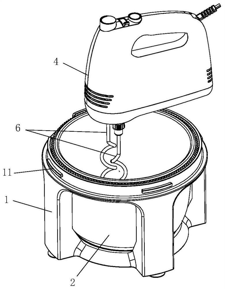
A technology of a mixer and a mixing mechanism, which is applied in the field of mixers, can solve the problems of poor rotation stability, high price, and poor work stability of a mixing bowl, and achieve the effects of preventing food splashing, improving mixing efficiency, and prolonging service life.

Pending Publication Date: 2020-11-24
GUANGDONG XINBAO ELECTRICAL APPLIANCES HLDG CO LTD
View PDF1 Cites 2 Cited by
  • Summary
  • Abstract
  • Description
  • Claims
  • Application Information

AI Technical Summary

Problems solved by technology

[0002] Existing mixers such as desktop egg beaters adopt a rotating shaft flip-up structure similar to a kitchen machine structure. This flip-type structure is relatively complicated, the product is large in size, poor in stability, and relatively expensive.
[0003] The Chinese patent application with the publication number CN107928467A discloses a transmission mechanism for the mixing bowl of an egg beater. Although the mixing bowl can also be rotated, a turntable is arranged under the mixing bowl, and the turntable is passed through the transmission member and the transmission shaft. The driving mixing rod assembly set above the mixing bowl is connected to drive the mixing bowl to rotate. The transmission process is from the top to the bottom of the egg beater. Poor stability; in addition, the patent application does not have a bowl cover, and the food may splash when stirring

Method used


Image

  • Stirring machine
  • Stirring machine
  • Stirring machine

Examples


Embodiment Construction

[0032] In order to make the purpose, technical solutions and advantages of the embodiments of the present invention more clear, the technical solutions of the embodiments of the present invention will be clearly and completely described below in conjunction with the drawings of the embodiments of the present invention.

[0033]Unless otherwise defined, the technical terms or scientific terms used in the present invention shall have the usual meanings understood by those skilled in the art to which the present invention belongs. "First", "second" and similar words used in the present invention do not indicate any order, quantity or importance, but are only used to distinguish different components. "Comprising" or "comprising" and similar words mean that the elements or items appearing before the word include the elements or items listed after the word and their equivalents, without excluding other elements or items. Words such as "connected" or "connected" are not limited to ph...


PUM


Abstract

The invention relates to a stirrer. The stirrer comprises a base, a stirring bowl, a bowl cover and a main machine. The stirring bowl is mounted in the base; the bowl cover is detachably connected with the top of the base, and a first transmission mechanism is arranged in the bowl cover; the main machine is detachably mounted on the bowl cover; and a driving mechanism is arranged in the main machine, the driving mechanism is connected with a stirring mechanism, the stirring mechanism can penetrate through the bowl cover to extend into the stirring bowl, a first transmission mechanism is arranged in the bowl cover, and the stirring mechanism is in transmission connection with the stirring bowl through the first transmission mechanism so as to drive the stirring bowl to rotate together whenthe driving mechanism drives the stirring mechanism to rotate and stir. The stirring mechanism is driven by the driving mechanism to rotate and stir, and meanwhile, the stirring bowl can be driven torotate together, so that the stirring efficiency and the stirring effect are effectively improved, stable operation of the stirring bowl can be guaranteed, food materials are prevented from splashingduring stirring, and the service life of the stirrer is prolonged; and in addition, all parts of the stirrer are convenient to disassemble and assemble, the size of the whole machine is small, and cost can be reduced.

Description

technical field [0001] The invention relates to the technical field of food mixing and cooking, in particular to a mixer. Background technique [0002] Existing mixers such as table-top egg beaters adopt a rotating shaft reversing structure similar to that of a chef's machine. The reversing structure is relatively complicated, the product is large in size, poor in working stability, and relatively expensive. [0003] The Chinese patent application with the publication number CN107928467A discloses a transmission mechanism for the mixing bowl of an egg beater. Although the mixing bowl can also be rotated, a turntable is arranged under the mixing bowl, and the turntable is passed through the transmission member and the transmission shaft. The driving mixing rod assembly set above the mixing bowl is connected to drive the mixing bowl to rotate. The transmission process is from the top to the bottom of the egg beater. Poor stability; In addition, the bowl cover is not provided ...

Claims


Application Information

Patent Timeline
Patent Type & Authority Applications(China)
IPC IPC(8): A47J43/044A47J43/07A47J43/08
CPCA47J43/044A47J43/0705A47J43/0711A47J43/082
Inventor 郭建刚彭晓林陈亮
Owner GUANGDONG XINBAO ELECTRICAL APPLIANCES HLDG CO LTD
Why Eureka
Try Eureka