
Agricultural corn threshing equipment

A corn threshing and equipment technology, applied in threshing equipment, applications, agriculture, etc., can solve problems such as low efficiency and difficulty in ensuring safety, and achieve the effect of preventing falling

Pending Publication Date: 2020-11-24
李华斌
View PDF6 Cites 7 Cited by
  • Summary
  • Abstract
  • Description
  • Claims
  • Application Information

AI Technical Summary

Problems solved by technology

[0004] In order to overcome the traditional threshing method relying on manual continuous control of the electric drill switch to thresh corn, the efficiency is not high, and the electric drill runs at a high speed, making it difficult for workers to ensure safety. The technical problem of the present invention is to provide a threshing process that does not require manual contact Relying on the device to automatically convey corn to ensure efficiency and safety of agricultural corn threshing equipment

Method used


Image

  • Agricultural corn threshing equipment
  • Agricultural corn threshing equipment
  • Agricultural corn threshing equipment

Examples


Embodiment 1

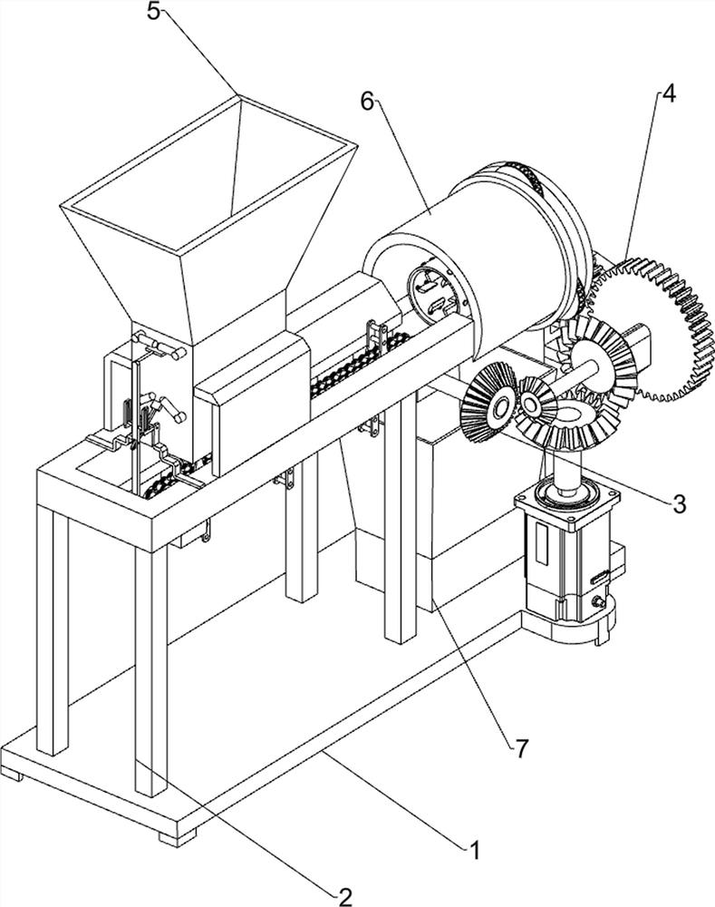
[0048] A kind of agricultural corn threshing equipment, such as figure 1 As shown, it includes a bottom plate 1, a first support frame 2, a pushing mechanism 3 and a threshing mechanism 4, the left side of the top of the bottom plate 1 is provided with a first support frame 2, and the upper part of the first support frame 2 is provided with a pushing mechanism 3. A threshing mechanism 4 is connected between the front side of the feeding mechanism 3 and the right side of the bottom plate 1 top.

[0049] When the staff needs to thresh the corn, first start the threshing mechanism 4 to drive the pushing mechanism 3 to work, then put the corn horizontally on the top of the first support frame 2, and the pushing mechanism 3 works to transfer the corn to the threshing mechanism 4 Inside, the threshing mechanism 4 can thresh the corn, after the threshing is completed, stop the threshing mechanism 4, and the staff can collect it again.

Embodiment 2

[0051] On the basis of Example 1, such as figure 2 As shown, the pusher mechanism 3 includes a first bearing seat 30, a chain set 31, a pusher head 32, a first rotating shaft 33 and a differential bevel gear set 34, and the top of the first support frame 2 is U-shaped with an opening on the right side. Both sides of the bottom of the first support frame 2 are symmetrically provided with a first bearing seat 30, and a chain group 31 is rotatably connected between the first bearing seat 30, and a pusher head 32 is evenly arranged on the chain group 31, and the first bearing on the right side The front side of the seat 30 is rotatably provided with a first rotating shaft 33, and a differential bevel gear set 34 is provided between the front side of the first rotating shaft 33 and the left side of the threshing mechanism 4.

[0052] After the corn is placed on the chain group 31 in the top of the first support frame 2, the threshing mechanism 4 drives the first rotating shaft 33 ...


PUM


Abstract

The invention relates to threshing equipment, in particular to agricultural corn threshing equipment. According to the agricultural corn threshing equipment, manual contact with the threshing processis not needed, corns are automatically conveyed through the device, and efficiency and safety are guaranteed. The agricultural corn threshing equipment comprises a first supporting frame, wherein a first supporting frame pushing mechanism is arranged on the left side of the top of a bottom plate; a pushing mechanism is arranged on the upper portion of the first supporting frame; and a threshing mechanism is connected between the front side of the pushing mechanism and the right side of the top of the bottom plate. Through the arrangement of a discharging bin and a funnel, a worker can directlyput corns in the equipment and sequentially conduct conveying and threshing; and a pushing head is arranged on a chain group, so that corns can be directly pushed into a threshing cylinder to be threshed.

Description

technical field [0001] The invention relates to a threshing equipment, in particular to an agricultural corn threshing equipment. Background technique [0002] Corn is an annual herbaceous plant of Poaceae. It is an important food crop in the world. Corn has high nutritional value and is an excellent food crop. It is an important feed source and one of the indispensable raw materials for food, medical and health, light industry, chemical industry, etc. Because corn resources are extremely rich, cheap and easy to obtain, they also have many biological activities, such as anti-oxidation, anti-tumor, anti-tumor It has broad development and application prospects. [0003] The edible part of corn is its corn kernels. Corn threshing takes a lot of time and energy. Modern people usually buy corn kernels directly, so suppliers will thresh corn before selling. The traditional threshing method inserts the bottom of the corn into the electric On the drill bit, start the electric dril...

Claims


Application Information

Patent Timeline
Patent Type & Authority Applications(China)
IPC IPC(8): A01F11/06A01F12/12A01F12/18
CPCA01F11/06A01F12/12A01F12/18
Inventor 李华斌
Owner 李华斌
Learn More