
High-speed stubble cleaning harrow

A high-speed technology for stubble removal, applied in the field of stubble removal rakes, can solve problems such as the deviation of the tractor’s travel direction, and achieve the effects of improving operation quality, facilitating transportation, and preventing missing stubble removal

Pending Publication Date: 2020-11-24
宜兴博登泰科工业装备有限公司
View PDF1 Cites 2 Cited by
  • Summary
  • Abstract
  • Description
  • Claims
  • Application Information

AI Technical Summary

Problems solved by technology

[0005] In order to solve the problem that the stubble harrow in the prior art is likely to cause the tractor to deviate in the direction of travel when it works on sloped or high-lying uneven ground, the present invention provides a high-speed stubble harrow, and the adopted technical scheme is as follows:

Method used


Image

  • High-speed stubble cleaning harrow
  • High-speed stubble cleaning harrow
  • High-speed stubble cleaning harrow

Examples


Embodiment 1

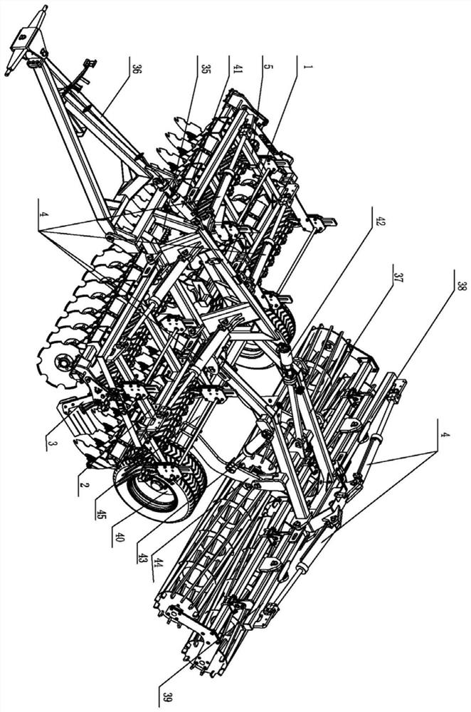
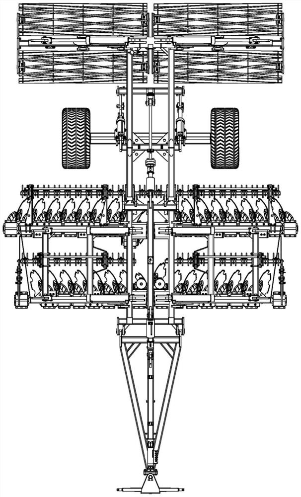
[0063] The high-speed stubble harrow includes the main rake assembly 1, the middle rake assembly 35, the left folding rake assembly 2, and the right folding rake assembly 5. The left folding rake assembly 2 and the right folding rake assembly 5 can be It is connected to the left and right sides of the main rake assembly 1 in a folded manner, the middle rake assembly 35 is fixedly connected under the main rake assembly 1, and the front end of the main rake assembly 1 is movably connected with The traction frame assembly 36, the rear end of the main rake assembly 1 is movably connected with a rear adjusting tailstock assembly 37, and the rear left and right sides of the rear adjusting tailstock assembly 37 are respectively connected with a left folding pressing roller assembly 39 and a right folding roller assembly 39. The pressure roller assembly 38, the lower end of the rear adjusting tailstock 37 is connected with two road wheels 40, the two road wheels 40 are connected by an ...

Embodiment 2

[0068] On the basis of Example 1, the front row of the middle rake frame is also symmetrically provided with a third rake 9, and the third rake 9 is located outside the first rake 8 and the second rake 7, The concave side surface of the third rake piece 9 faces outward and forward obliquely.

Embodiment 3

[0070] The difference from Example 2 is that the fourth rake blade and the fifth rake blade are located in the rear row of the middle rake frame, the fourth rake blade and the fifth rake blade are arranged face to face, and the The fourth rake is shifted forward in the direction of traction relative to the fifth rake, and the concave sides of the fourth rake and the fifth rake are obliquely facing inward and forward; the middle rake The rear position of the rear row is also symmetrically provided with a sixth rake, the sixth rake is located on the outside of the fourth rake and the fifth rake, and the concave side of the sixth rake is inclined towards the inside and toward the ahead.


PUM


Abstract

The invention discloses a high-speed stubble cleaning harrow. The high-speed stubble cleaning harrow comprises a main harrow frame assembly, a middle harrow frame assembly, a left folding harrow frameassembly and a right folding harrow frame assembly, wherein the left folding harrow frame assembly and the right folding harrow frame assembly are connected to the left side and the right side of themain harrow frame assembly in a foldable mode, and the rear end of the main harrow frame assembly is movably connected with a rear adjusting tailstock assembly; a left folding press roller assembly and a right folding press roller assembly are connected to the left side and the right side of the rear portion of the rear adjusting tailstock assembly respectively, two walking wheels are connected to the lower end of the rear adjusting tailstock, the two walking wheels are connected through an axle, and the axle is connected with the rear adjusting tailstock through a connecting arm; and the harrow blades on the left-right harrow frame and the front-back harrow frame are symmetrically designed, lateral traction force is avoided, power is exerted more sufficiently, and oil consumption is reduced.

Description

technical field [0001] The invention relates to a stubble removal harrow, in particular to a high-speed stubble removal harrow. Background technique [0002] According to the requirements of the current national environmental protection policy, straw burning is not allowed, and straw, as a kind of biomass energy, can be comprehensively utilized. Mechanized straw returning to the field is one of the ways to comprehensively utilize straw. [0003] The stubble harrow plays a vital role in the process of mechanized straw returning to the field. The application number is CN201910494823.7, and the prior art titled "Single-body rapid stubble removal hydraulic folding rake" provides a single-unit rapid stubble removal hydraulic folding rake. The rake includes the main traction beam, the main frame, the harrowing general bearing, the crushing roller general bearing, the traveling wheel and the depth adjustment wheel. The main traction beam is connected with the main frame by pins, an...

Claims


Application Information

Patent Timeline
IPC IPC(8): A01B21/08A01B23/06A01B23/04A01B29/04A01B49/02
CPCA01B21/08A01B23/046A01B23/06A01B29/04A01B49/022
Inventor 向洪鑫王林峰朱海涛陈广陈少良
Owner 宜兴博登泰科工业装备有限公司
Learn More