
Nylon pipe shaping device

A nylon and U-shaped technology, which is applied in the field of nylon tubes, can solve the problems of poor setting effect of nylon tube setting devices, and achieve the effect of improving the setting effect

Inactive Publication Date: 2020-11-20
十堰铁马汽车零部件有限公司
View PDF0 Cites 0 Cited by
  • Summary
  • Abstract
  • Description
  • Claims
  • Application Information

AI Technical Summary

Problems solved by technology

[0004] The purpose of the present invention is to solve the problem that the setting effect of the nylon tube setting device in the prior art is poor, and a kind of nylon tube setting device proposed

Method used


Image

  • Nylon pipe shaping device
  • Nylon pipe shaping device
  • Nylon pipe shaping device

Examples


Embodiment Construction

[0020] The following will clearly and completely describe the technical solutions in the embodiments of the present invention with reference to the accompanying drawings in the embodiments of the present invention. Obviously, the described embodiments are only some, not all, embodiments of the present invention.

[0021] In describing the present invention, it should be understood that the terms "upper", "lower", "front", "rear", "left", "right", "top", "bottom", "inner", " The orientation or positional relationship indicated by "outside", etc. is based on the orientation or positional relationship shown in the drawings, and is only for the convenience of describing the present invention and simplifying the description, rather than indicating or implying that the referred device or element must have a specific orientation, so as to Specific orientation configurations and operations, therefore, are not to be construed as limitations on the invention.

[0022] refer to Figure ...


PUM


Abstract

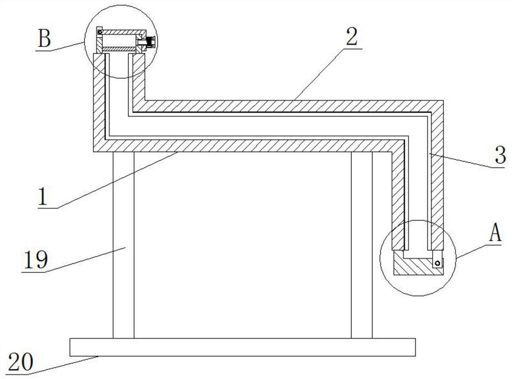
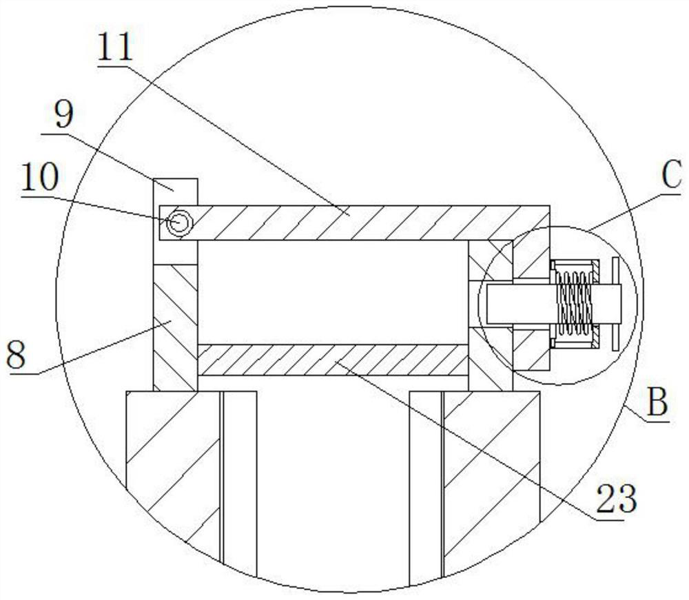
The invention relates to the technical field of nylon pipes, and discloses a nylon pipe shaping device. The nylon pipe shaping device comprises a lower die plate and an upper die plate, wherein circular grooves are formed in the side walls of the sides, opposite to each other, of the upper die plate and the lower die plate; a fixing plate is fixedly connected to the lower end of the lower die plate, and a rotating plate is fixedly connected to the lower end of the upper die plate; a fixing shaft is fixedly connected to the side wall of the front side of the fixing plate, a shaft hole is formedin the side wall of the front side of the rotating plate, and the fixing shaft penetrates through the rotating plate through the shaft hole; a mounting plate is fixedly connected to the upper end ofthe lower die plate, and a U-shaped groove is formed in the side wall of the upper side of the mounting plate; and a rotating shaft is fixedly connected between the groove walls of the opposite sidesof the U-shaped groove, and the rotating shaft is movably provided with an L-shaped buckle plate in a sleeved mode. The nylon pipe shaping device can comprehensively shape the nylon pipes, and the shaping effect is effectively improved.

Description

technical field [0001] The invention relates to the technical field of nylon tubes, in particular to a nylon tube shaping device. Background technique [0002] Nylon brake tube is an important part of the car brake system. Before the nylon tube is assembled, the nylon tube needs to be shaped, so that the shape of the nylon tube can be adapted to the installation requirements, and the installation of the nylon tube can be more neat. [0003] The existing nylon tube sizing device is to bind the nylon tube on the sizing mold. This sizing method can only bind some parts, resulting in poor sizing effect of the unbound parts and affecting the final sizing effect. Contents of the invention [0004] The object of the present invention is to solve the problem that the nylon tube shaping device in the prior art has a poor shaping effect, and propose a nylon tube shaping device. [0005] In order to achieve the above object, the present invention adopts the following technical solut...

Claims


Application Information

Patent Timeline
IPC IPC(8): B29C53/20B29C53/80B29C33/30B29K77/00B29L23/00
CPCB29C33/303B29C53/20B29C53/80B29K2077/00B29L2023/22
Inventor 洪昌炎方欣洪昌军
Owner 十堰铁马汽车零部件有限公司
Learn More