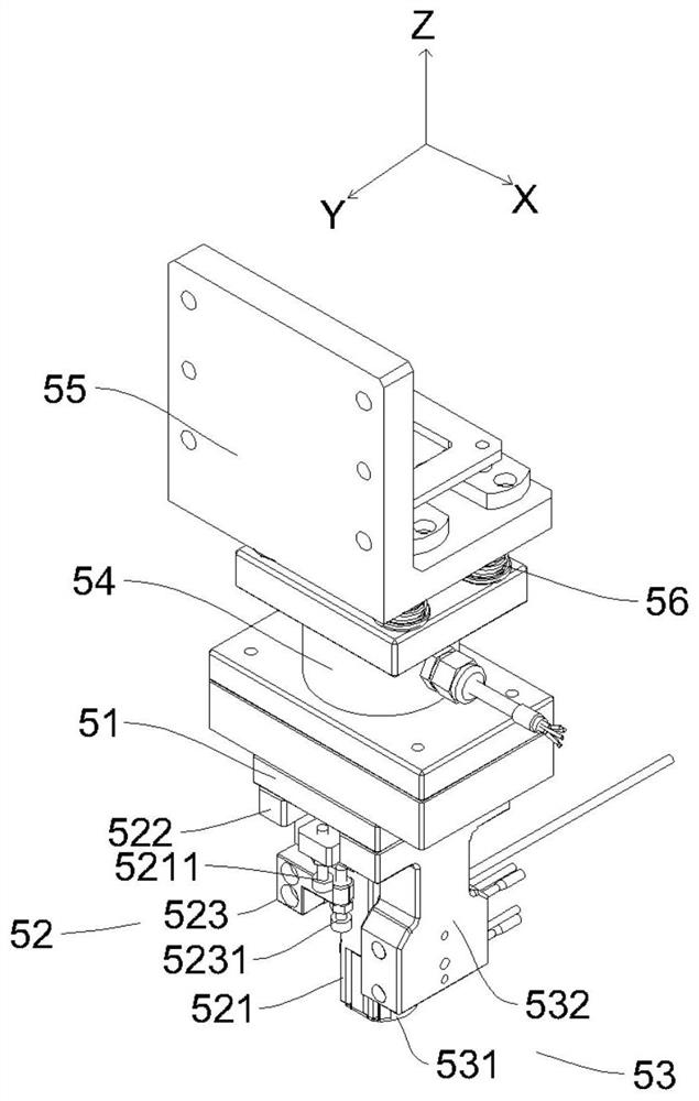
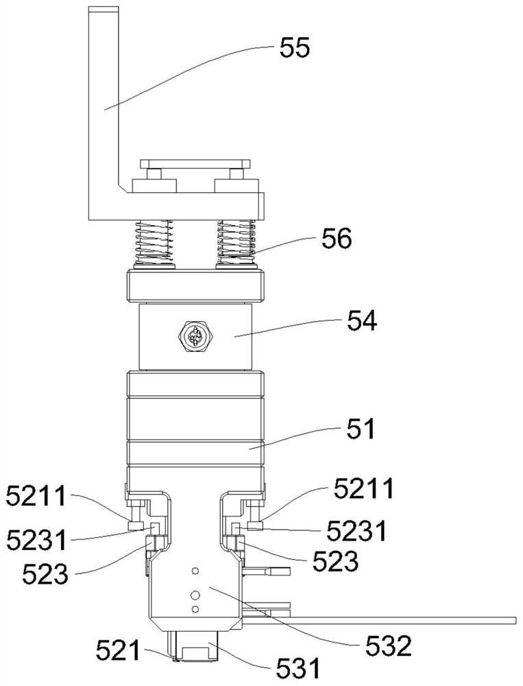
Automatic pressure maintaining mechanism

An automatic and indenter technology, which is applied in the direction of workpiece clamping devices and manufacturing tools, can solve the problems of pressure holding failure, low success rate of pressure holding, and inability of the pressure holding device to constantly monitor the holding pressure, so as to prevent it from being crushed , Improve the effect of pressure holding efficiency

Pending Publication Date: 2020-11-20
SUZHOU RS TECH
View PDF0 Cites 4 Cited by
  • Summary
  • Abstract
  • Description
  • Claims
  • Application Information

AI Technical Summary

Problems solved by technology

[0002] On non-standard automation equipment, it is often necessary to hold the assembled product for a period of time to ensure that the assembled product has excellent structural stability and reliability. There are several problems in the existing pressure holding device: first , the degree of automation is low, and there are many steps that require manual assistance, resulting in a low success rate of pressure holding and unsatisfactory pressure holding effects; secondly, most of them use off-line pressure holding tests, that is, after the product assembly is completed, the product needs to be transferred from the production line to the holding Pressure maintaining in the pressure device, and problems such as product misalignment are often prone to occur during the transfer process, which affects the stability and reliability of the product structure. In addition, the off-line pressure maintaining steps are cumbersome and the degree of automation is low, resulting in low pressure maintaining efficiency; again, The existing pressure holding device cannot constantly monitor the holding pressure, and it is prone to pressure holding failure caused by insufficient holding pressure or product damage caused by excessive holding pressure

Method used


Image

  • Automatic pressure maintaining mechanism
  • Automatic pressure maintaining mechanism
  • Automatic pressure maintaining mechanism

Examples


Embodiment Construction

[0025] The present invention will be further described in detail below in conjunction with the accompanying drawings, and the aforementioned and other objects, features, aspects and advantages of the present invention will become more apparent, so that those skilled in the art can implement them with reference to the description. In the drawings, the shapes and dimensions may be exaggerated for clarity, and the same reference numerals will be used throughout to designate the same or like parts. In the following description, terms such as center, thickness, height, length, front, back, rear, left, right, top, bottom, upper, lower, etc. are based on the orientation or positional relationship shown in the drawings. In particular, "height" corresponds to the dimension from top to bottom, "width" corresponds to the dimension from left to right, and "depth" corresponds to the dimension from front to back. These relative terms are for convenience of description and are generally not ...


PUM


Abstract

The invention discloses an automatic pressure maintaining mechanism. The automatic pressure maintaining mechanism comprises a connecting plate, a first pressure maintaining assembly and a second pressure maintaining assembly, wherein the first pressure maintaining assembly and the second pressure maintaining assembly are arranged below the connecting plate; the first pressure maintaining assemblyand the second pressure maintaining assembly are matched with each other in structure, the first pressure maintaining assembly and the second pressure maintaining assembly maintain the pressures of different parts of a workpiece correspondingly, and the first pressure maintaining assembly and the second pressure maintaining assembly have different pressure maintaining pressures on the workpiece. The automatic pressure maintaining mechanism has the beneficial effects that the pressure maintaining pressures can be monitored in real time while the pressure maintaining efficiency is improved, so that a product is prevented from being crushed while it is guaranteed that enough pressure maintaining pressure is provided.

Description

technical field [0001] The invention relates to the field of mechanical automation. More specifically, the present invention relates to an automatic pressure maintaining mechanism. Background technique [0002] On non-standard automation equipment, it is often necessary to hold the assembled product for a period of time to ensure that the assembled product has excellent structural stability and reliability. There are several problems in the existing pressure holding device: first , the degree of automation is low, and there are many steps that require manual assistance, resulting in a low success rate of pressure holding and unsatisfactory pressure holding effects; secondly, most of them use off-line pressure holding tests, that is, after the product assembly is completed, the product needs to be transferred from the production line to the holding Pressure maintaining in the pressure device, and problems such as product misalignment are often prone to occur during the trans...

Claims


Application Information

Patent Timeline
IPC IPC(8): B25B11/00
CPCB25B11/00
Inventor 缪磊袁文卿周永昌吴建武徐雨舟
Owner SUZHOU RS TECH
Why Eureka
Try Eureka