
Automatic pressure maintaining machine

A press and automatic technology, applied in lamination, lamination device, lamination auxiliary operation, etc., can solve the problems of low production efficiency, high labor intensity, high production cost, etc., to improve production efficiency, liberate labor force, maintain The effect of high pressure efficiency

Inactive Publication Date: 2021-04-23
苏州市朗电机器人有限公司
View PDF0 Cites 0 Cited by
  • Summary
  • Abstract
  • Description
  • Claims
  • Application Information

AI Technical Summary

Problems solved by technology

[0002] With the development of science and technology, the production of more and more electronic products is automated, which greatly speeds up the production efficiency. In order to protect the products, film protection is required after the production is completed, especially the screens of electronic products, which need film protection. Putting scratches and dust on the product will affect the use and appearance of the product
[0003] After the screen is covered with film, in order to ensure the firmness of the film, it is generally necessary to put it into the pressure-holding equipment for static pressure-holding. The current pressure-holding equipment can only maintain pressure for a limited number of 1-3 products at a time, and the pressure-holding is in the production line. In addition, other production activities cannot be carried out during pressure holding, which is time-consuming and laborious, and the production efficiency is low. Another pressure holding device is to manually place the screen in the pressure holding cabin, and then manually record the time. After the pressure holding is completed, it is sent out manually , high labor intensity and high production cost

Method used


Image

  • Automatic pressure maintaining machine

Examples


Embodiment Construction

[0014] The present invention will be further described below in conjunction with accompanying drawing.

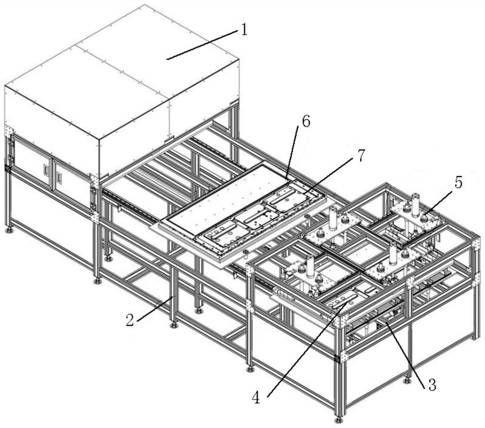
[0015] according to figure 1 The shown automatic pressure maintaining machine of the present invention comprises a hood, and a pressure maintaining mechanism is arranged inside the hood, and the pressure maintaining mechanism includes a pressure maintaining box 1, a frame 2, and a closing mechanism 3. The pressure maintaining mechanism The box 1 and the closing mechanism 3 are arranged above the two ends of the frame 2. The closing mechanism 3 includes a support plate, and the side of the support plate is provided with a carrier warehouse 4 and a pressure maintaining cylinder 5. The closing mechanism 3 is also provided with a three-axis Manipulator, the upper surface of the frame 2 is provided with a guide rail, and the frame 2 is also provided with a transfer device 6, the transfer device 6 is slidingly connected with the guide rail, and the transfer device 6 is a panel, a...


PUM


Abstract

The invention discloses an automatic pressure maintaining machine, which comprises a machine cover, wherein a pressure maintaining mechanism is arranged in the machine cover, the pressure maintaining mechanism comprises a pressure maintaining box, a machine frame and a sealing mechanism, the pressure maintaining box and the sealing mechanism are arranged above the two ends of the machine frame, a carrier bin and a pressure maintaining air cylinder are arranged on the side surface of a supporting plate, the sealing mechanism is further provided with a three-axis manipulator, a transfer device is further arranged on the machine frame, the transfer device is in sliding connection with a guide rail, a carrier frame is arranged on the upper surface of the panel, a plurality of carriers are placed in the carrier bin, and a control device is further arranged in the machine cover. The automatic pressure maintaining machine is simple in structure and convenient to operate, automatic feeding is achieved through the manipulator, automatic pressure maintaining is achieved through the pressure maintaining air cylinder, the transfer device is used for carrying the carriers, and finally, the carriers subjected to pressure maintaining are placed in a material storage cavity in a centralized mode for pressure maintaining, so that unmanned operation is achieved in the whole process, labor force is liberated, the production efficiency is improved, and the pressure maintaining efficiency is high.

Description

technical field [0001] The invention relates to the technical field of automatic production equipment, in particular to an automatic pressure maintaining machine. Background technique [0002] With the development of science and technology, the production of more and more electronic products is automated, which greatly speeds up the production efficiency. In order to protect the products, film protection is required after the production is completed, especially the screens of electronic products, which need film protection. Scratches and dust will affect the use and appearance of the product. [0003] After the screen is covered with film, in order to ensure the firmness of the film, it is generally necessary to put it into the pressure-holding equipment for static pressure-holding. The current pressure-holding equipment can only maintain pressure for a limited number of 1-3 products at a time, and the pressure-holding is in the production line. In addition, other productio...

Claims


Application Information

Patent Timeline
Patent Type & Authority Applications(China)
IPC IPC(8): B32B37/10B32B38/00B32B38/18
CPCB32B37/1009B32B38/00B32B38/0012B32B38/18B32B2038/1891
Inventor 张泳宋玮
Owner 苏州市朗电机器人有限公司
Learn More