
Method for reducing negative pressure at bottom of plane gate and plane gate structure thereof

A plane gate and negative pressure technology, which is applied in water conservancy projects, sea area projects, coastline protection, etc., can solve the problems that the gate cannot be closed due to moving water, it is difficult to find air replenishment measures, and the gate is difficult to open and close, so as to achieve processing and transformation Simple, reduce the opening and closing force, and the effect of smooth operation of the gate

Active Publication Date: 2020-11-17
YELLOW RIVER ENG CONSULTING
View PDF9 Cites 0 Cited by
  • Summary
  • Abstract
  • Description
  • Claims
  • Application Information

AI Technical Summary

Problems solved by technology

However, the bottom edge of the door leaf is affected by the outlet water flow, so it is difficult to find air supply measures. Some use holes in the web of the main beam at the bottom of the plane gate to supply air through the upper cavity of the bottom beam, but the flow at the top of the gate is often sealed. The air intake channel, so the pulsation at the bottom edge due to negative pressure makes it difficult to open and close the gate, and even causes the gate to fail to close or the wire rope to be broken.

Method used


Image

  • Method for reducing negative pressure at bottom of plane gate and plane gate structure thereof
  • Method for reducing negative pressure at bottom of plane gate and plane gate structure thereof

Examples


Embodiment Construction

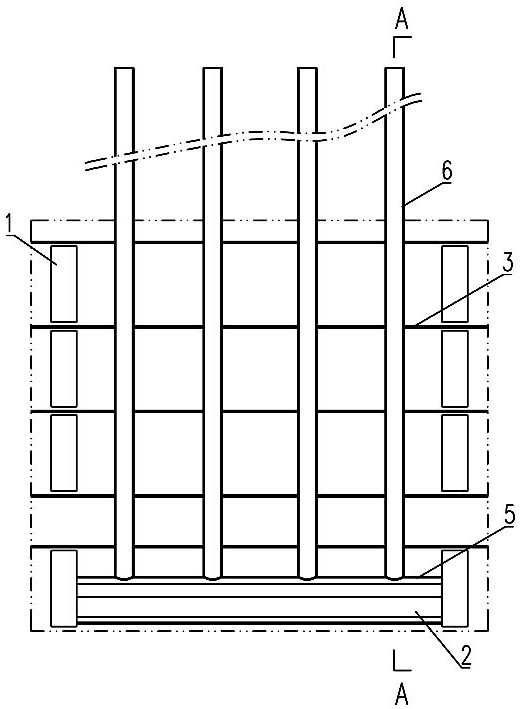
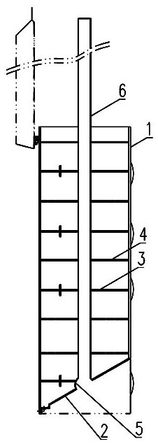
[0016] The embodiments of the present invention will be described in detail below in conjunction with the accompanying drawings. This embodiment is implemented on the premise of the technical solution of the present invention, and detailed implementation methods and specific operating procedures are provided, but the scope of protection of the present invention is not limited to the following Described embodiment.

[0017] Such as figure 1 , 2 As shown, the method for reducing the negative pressure at the bottom of the plane gate according to the present invention comprises the following steps:

[0018] Step 1, the lower part of the sand-retaining plane gate is set as a double-panel box-type door leaf 1, and the height of the double-panel box-type door leaf 1 is higher than that of the upper and downstream sides of the double-panel box-type door leaf 1. The viscous force of sediment around the panel box-type door leaf 1; the bottom edge sealing plate 2 of the double-panel bo...


PUM


Abstract

The invention discloses a method for reducing negative pressure at the bottom of a plane gate and a plane gate structure thereof. The method comprises the following steps: 1, setting the lower part ofa sand blocking plane gate as a double-panel box type gate leaf, wherein a bottom edge sealing plate of the double-panel box type gate leaf is an inclined plane which is inclined towards the upper part of the downstream side, and a water leakage opening is formed in a cross beam web in the double-panel box type gate leaf; and 2, transversely arranging an arc pipe groove with a downward opening inthe plate surface of the bottom edge sealing plate along the plane gate, then arranging a vertical pipe in the double-panel box type gate leaf, wherein the vertical pipe penetrates through the crossbeam web in the double-panel box type gate leaf, a lower pipe opening of the vertical pipe is communicated with the arc pipe groove, and an upper pipe opening of the vertical pipe extends out of the upper part of the sand blocking plane gate, so that the effects of supplementing air to the lower part of the sand blocking plane gate when the upper pipe opening of the vertical pipe is higher than the water surface and supplementing water to the lower part of the sand blocking plane gate when the upper pipe opening of the vertical pipe is lower than the water surface are achieved. According to the method and the plane gate structure, the problem that the opening and closing of the sand blocking plane gate are influenced due to the fact that the lower part of the gate generates negative pressure due to sediment accumulation is solved, and the viscous force of a single-side gate panel is greatly reduced.

Description

technical field [0001] The invention relates to a sand-retaining planar gate in a water conservancy project, in particular to a method for reducing negative pressure at the bottom of the planar gate and a planar gate structure. Background technique [0002] In view of the characteristics of rivers with a lot of sediment, in order to prevent sedimentation in the sand discharge tunnel in the water conservancy project, it is necessary to install a sand retaining plane gate at the entrance of the sand discharge tunnel. However, the influence of sediment on the opening and closing force of the gate is not stipulated in the water conservancy industry standards, and it is often determined according to experiments. The test gate is simulated by a steel plate, and the design conditions are all with sediment on one side. Therefore, the comprehensive viscosity index of the sediment on the gate panel and the gate slot given by the test is difficult to open and close during the actual pr...

Claims


Application Information

Patent Timeline
Patent Type & Authority Applications(China)
IPC IPC(8): E02B7/20E02B8/00
CPCE02B7/20E02B8/00
Inventor 景来红杨顺群诸葛梅君
Owner YELLOW RIVER ENG CONSULTING
Learn More