
Tile sticking robot system

A robot system and tiling technology, which is applied in manipulators, program-controlled manipulators, construction, etc., can solve problems such as uneven product quality, high labor costs, and low work efficiency, so as to improve construction efficiency, shorten construction period, and save labor cost effect

Pending Publication Date: 2020-11-17
CHINA CONSTR SCI & TECH CO LTD
View PDF0 Cites 6 Cited by
  • Summary
  • Abstract
  • Description
  • Claims
  • Application Information

AI Technical Summary

Problems solved by technology

[0004] The technical problem to be solved by the present invention is to provide a robot system for tiling tiles, aiming at the problems of uneven product quality, low work efficiency and high labor cost in the prior art when tiling tiles manually.

Method used


Image

  • Tile sticking robot system
  • Tile sticking robot system
  • Tile sticking robot system

Examples


Embodiment 1

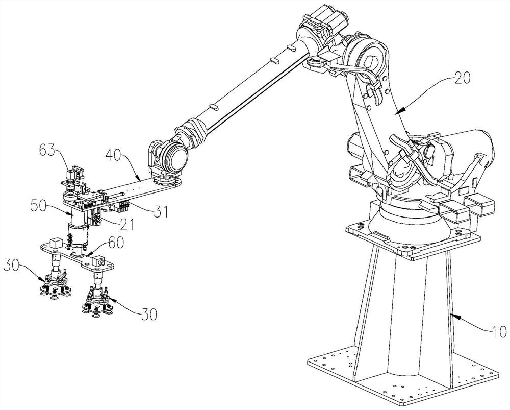
[0026] See figure 1 and figure 2 , shows Embodiment 1 provided by the present invention, a tile laying robot system, which includes a robot base 10, a six-axis robot 20, a manipulator and a controller. The manipulator includes a suction cup gripper 30 , a detector for detecting whether there are tiles, a horizontally extended arm 40 and a vertically elevated arm 50 . The six-axis robot 20 is fixed on the robot base 10, one end of the extended arm 40 is fixed on the power output end of the six-axis robot 20, the other end of the extended arm 40 is connected to the top of the raised arm 50, and the suction cup gripper 30 is installed on the extended arm 40. The bottom end of the high arm 50.

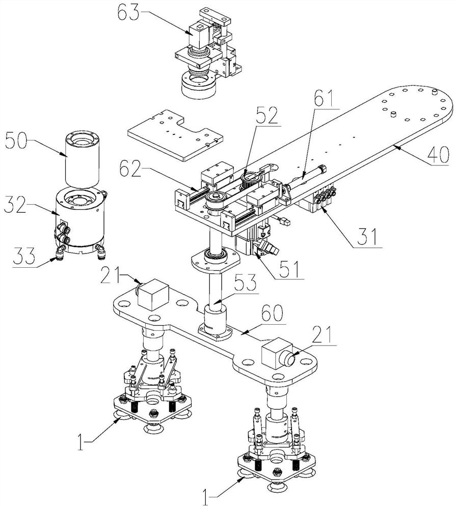
[0027] Among them, see image 3 and image 3 , the suction cup gripper 30 includes a vacuum suction cup 1, a vacuum generator system, a telescoping mechanism and a buffer mechanism.

[0028] The above-mentioned vacuum generator system includes a vacuum generator 31 , an air guide sli...

Embodiment 2

[0042] See Figure 6 and Figure 7 , shows a robot system for tiling tiles provided in this embodiment, which differs from Embodiment 1 in that:

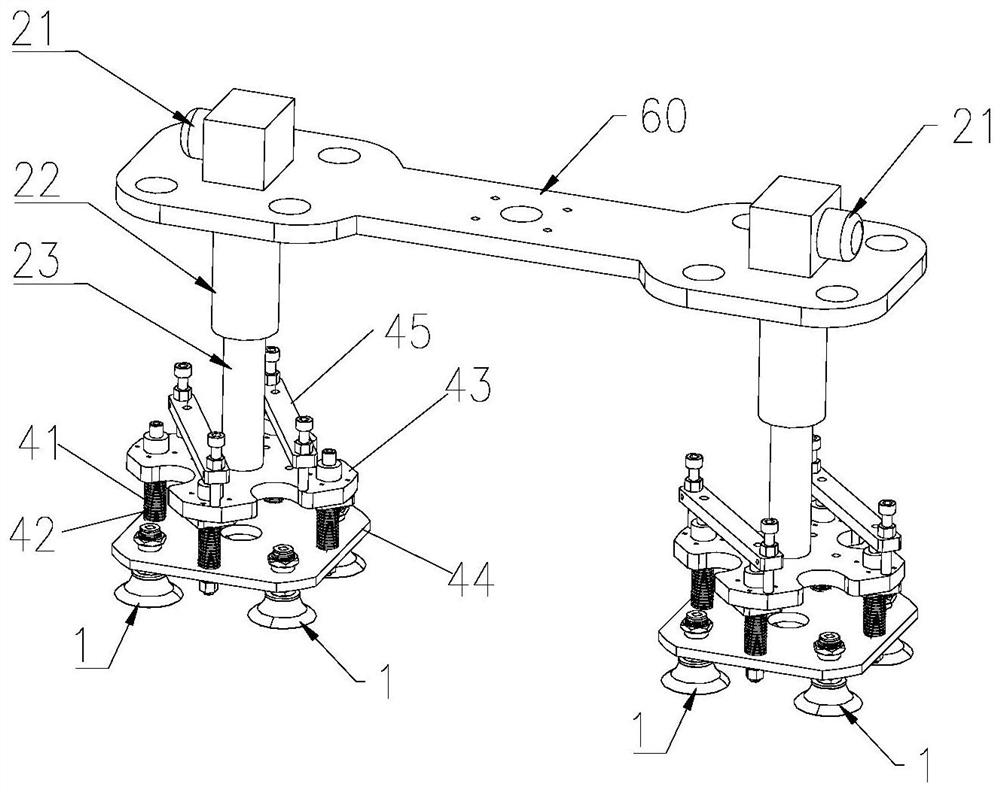
[0043] The manipulator of the tiling robot system in this embodiment includes an extension arm 40 and two suction cup grippers 30, one end of the extension arm 40 is used to connect with the six-axis robot 20, and the two sides of the other end of the extension arm 40 are respectively A suction cup gripper 30 is installed.

[0044] The suction cup gripper 30 also includes an extension rod 5, the length direction of the extension rods 5 on both sides is perpendicular to the length direction of the extension arm 40, one end of the extension rod 5 is fixedly connected with the extension arm 40, and the other end is connected with the extension arm 40. The vacuum chuck 1 is fixedly connected.

[0045] The tiling robot system of this embodiment has two suction cup grippers 30, which can grab two tiles 200 in one reciprocating movement...


PUM


Abstract

The invention provides a tile sticking robot system. The tile sticking robot system comprises a robot base, a six-axis robot, a mechanical arm and a controller; the mechanical arm comprises a sucker gripper and a detector used for detecting whether tiles exist or not; the sucker gripper comprises a vacuum sucker and a vacuum generator system; the controller controls the six-axis robot to move thevacuum sucker to the position above the tiles and controls the vacuum generator system to conduct suction, so that negative air pressure is formed in the vacuum sucker to suck the tiles; and then thesucker gripper is moved to the position above a product needing to be stuck, the vacuum generator system is controlled to inflate the vacuum sucker, zero air pressure / positive air pressure is formed in the vacuum sucker to be disengaged from the tiles, and therefore tile sticking is completed. According to the tile sticking robot system, manual tile sticking can be effectively replaced, conversionfrom building construction to industrialization is achieved, the tiled floor tile effect can be unified, and the construction quality requirement is met; and the construction efficiency can be effectively improved, the construction period is shortened and the labor cost is saved.

Description

technical field [0001] The invention belongs to the field of building construction, in particular to a robot system for tiling tiles. Background technique [0002] Laying ceramic tiles mainly adopts manually to carry out in the existing building construction process. There are mainly following defects in manual tiling process: [0003] The working environment during the construction process is relatively poor, and the harmful substances produced during the construction process will damage the health of workers. At the same time, the experience level of workers in construction is uneven, and the quality of products varies from person to person. The quality and appearance of tiles pasted by different workers are quite different. The construction speed of the workers is relatively slow, and the work efficiency is relatively low. Finally, with the development of society, labor costs are getting higher and higher, and the use of industrial robots to automatically install tiles...

Claims


Application Information

Patent Timeline
IPC IPC(8): B25J9/16B25J11/00B25J15/06E04F21/22E04F21/20
CPCB25J9/16B25J9/1694B25J11/00B25J15/0616E04F21/20E04F21/22
Inventor 齐贺张仲华袁媛全春楼郭强郭慧敏王欣博田文超张一
Owner CHINA CONSTR SCI & TECH CO LTD
Learn More