Impurity removing device for removing iron impurities in feed raw materials

A technology for feed raw materials and impurities, which is applied in the field of impurity removal devices for removing iron impurities in feed raw materials, can solve the problems of large density and volume, poor impurity removal effect, etc., and achieves excellent effects.

Pending Publication Date: 2020-11-17
申亚生物科技股份有限公司
View PDF6 Cites 0 Cited by
  • Summary
  • Abstract
  • Description
  • Claims
  • Application Information

AI Technical Summary

Problems solved by technology

At the same time, the utility model is also equipped with a demagnetization scraper to clean the adsorbed iron impurities, and its effect is better than that of the former. During the process, it will be buried in the lower layer of raw materials, so it cannot be effectively adsorbed when passing through the ring-shaped box, resulting in poor impurity removal effect

Method used


Image

  • Impurity removing device for removing iron impurities in feed raw materials
  • Impurity removing device for removing iron impurities in feed raw materials
  • Impurity removing device for removing iron impurities in feed raw materials

Examples


Embodiment 1

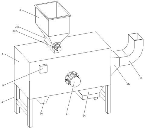
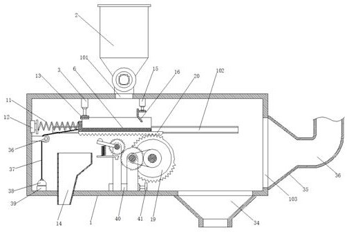
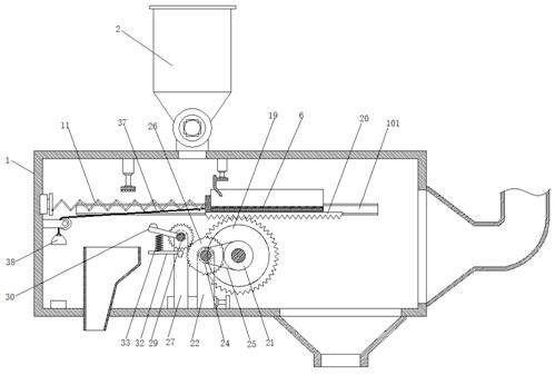
[0038] Embodiment 1 introduces a kind of impurity removal device for removing iron impurities in feed raw materials, referring to the attached figure 1 , attached figure 2 And attached image 3 , its main structure includes a box body 1 and a storage bin 2. A feed inlet 101 is opened in the middle of the upper surface of the box body 1 , and the storage bin 2 is arranged at the feed inlet 101 . Legs 4 are provided at four corners of the lower surface of the box body 1 , and a PLC control box 5 is arranged on the outer surface of the box body 1 . A horizontal chute 102 is provided on the front and rear inner walls of the box body 1 , and a material receiving plate 6 is arranged inside the box body 1 , and the right end of the material receiving plate 5 is arranged below the feeding port 101 .

[0039] Reference attached Figure 4 , attached Figure 5 And attached Figure 6 , permanent magnets 7 are evenly arranged inside the material receiving plate 6, and side plates 8 ...

Embodiment 2

[0044] Embodiment 2 is improved in many aspects on the basis of Embodiment 1, which will be described in detail below.

[0045] The same part of this embodiment 2 and embodiment 1 will not be described again, the difference is that: this embodiment is also provided with a uniform discharge device at the lower end of the storage bin 2, refer to the attached figure 1 And attached Figure 8 , its uniform discharge device includes a cylinder 201 connected with the storage bin 2, the outer end surface of the cylinder 201 is provided with a stepper motor 202, and its stepper motor 202 is connected with the signal output end of the PLC control box 5, and A horizontal rotating rod 203 is connected to the end where the output shaft of the stepping motor 202 extends into the cylinder 201 , and a plurality of baffle plates 204 are uniformly arranged on the outer surface of the horizontal rotating rod 203 . The above setting of the present embodiment 2 controls the stepper motor 202 by t...


PUM


Abstract

The invention relates to the technical field of feed processing equipment, and particularly discloses an impurity removing device for removing iron impurities in feed raw materials. The device comprises a box body and a storage bin, a feeding port is formed in the middle of the upper surface of the box body, the storage bin is arranged at the feeding port, supporting legs are arranged on the lowersurface of the box body, a PLC control box is arranged on the outer surface of the box body, horizontal sliding grooves are formed in the front inner wall and the rear inner wall of the box body, anda material receiving plate is arranged in the box body; the right end of the material receiving plate is located below the feeding port, and permanent magnets are evenly arranged in the material receiving plate. Compared with an existing stirring type iron removal and conveying adsorption roller type iron removal device, the impurity removal device is more excellent in effect, iron impurities infeed raw materials can be comprehensively removed, the adsorbed iron impurities can be rapidly removed, an operator does not need to regularly remove the adsorbed impurities, the iron impurity removalprinciple is novel, and excellent effect is achieved.

Description

technical field [0001] The invention relates to the technical field of feed processing equipment, and specifically discloses an impurity removal device for removing iron impurities in feed raw materials. Background technique [0002] Feed raw materials refer to feeds that are derived from animals, plants, microorganisms or minerals in feed processing. The main components of feed raw materials are still grains, and various nutritional supplements are added. At present, feed production enterprises purchase a large amount of grain from foreign countries, and the grain raw materials they purchase often contain a large amount of iron impurities, and they are also easily mixed with various iron objects during the transportation and storage of grain raw materials. Iron impurities in grain raw materials will not only reduce the quality of the feed and affect the growth of animals, but more importantly, the iron impurities in the feed raw materials will easily cause huge losses to th...

Claims


Application Information

Patent Timeline
Patent Type & Authority Applications(China)
IPC IPC(8): B03C1/02B65G69/04
CPCB03C1/02B65G69/04
Inventor 谢继奎李赛徐邦伟
Owner 申亚生物科技股份有限公司
Why Eureka
Try Eureka