Strain detection device and strain detection method

A detection device and detection method technology, applied in the field of mechanical quantity detection, can solve problems such as external interference, noise and interference amplification, resistance change, etc., and achieve the effects of improving accuracy and reliability, reducing attenuation and interference, and reducing influence

Inactive Publication Date: 2020-11-13
GUANGDONG GOBAO ELECTRONICS TECH CO LTD +1
View PDF11 Cites 4 Cited by
  • Summary
  • Abstract
  • Description
  • Claims
  • Application Information

AI Technical Summary

Problems solved by technology

Due to the long space transmission distance from the strain gauge to the external circuit board, the signal is easily attenuated or subject to external interference during the transmission process, which affects the accuracy of the detection results, and the noise and interference will also be amplified during the signal amplification process, which is not conducive to Acquisition of real signals
In addition, since the strain gauge is very sensitive to temperature changes, when the ambient temperature changes, its resistance will change, which will easily have a negative impact on the measurement results and affect the accuracy of the test results

Method used


Image

  • Strain detection device and strain detection method
  • Strain detection device and strain detection method
  • Strain detection device and strain detection method

Examples


Embodiment Construction

[0045] In order to enable those skilled in the art to better understand the technical solution of the present invention, the technical solution of the present invention will be further described below in conjunction with the accompanying drawings and through specific implementation methods.

[0046] In the description of the present invention, it should be noted that the terms "upper", "lower", "left", "right", "vertical", "horizontal", "inner", "outer" etc. The positional relationship is based on the orientation or positional relationship shown in the drawings, or the orientation or positional relationship that is usually placed when the product is used. Certain orientations, constructed and operative in certain orientations, therefore are not to be construed as limitations on the invention. In addition, the terms "first" and "second" are only used for descriptive purposes, or for distinguishing different structures or components, and should not be understood as indicating or...


PUM


Abstract

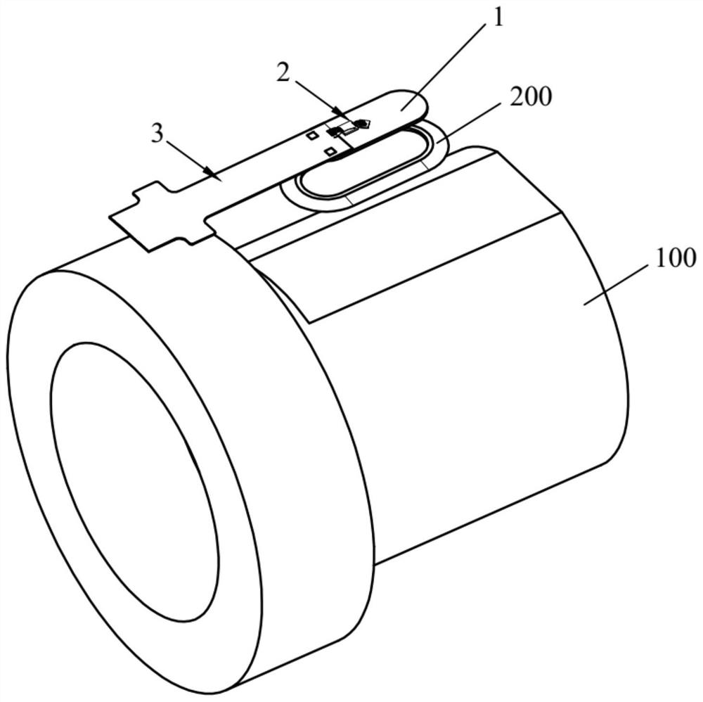
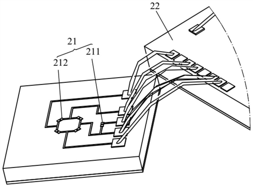
The invention relates to the technical field of mechanical quantity detection, in particular to a strain detection device and a strain detection method. The strain detection device comprises a substrate, a detection assembly and an output terminal, wherein the substrate is configured to be mounted on a detected carrier, the detection assembly is fixed on the substrate, the detection assembly comprises a strain sensing module and a signal processing module which are arranged at an interval, and the strain sensing module is electrically connected with the signal processing module; one end of theoutput terminal is fixed on the substrate and is electrically connected with the signal processing module, and the other end of the output terminal is configured to be electrically connected with anexternal controller. According to the strain detection device, the strain sensing module and the signal processing module are both installed on the detected carrier, so that the signal transmission distance between the strain sensing module and the signal processing module is shortened, and attenuation and interference in the signal transmission process are reduced; the strain sensing modules andthe signal processing modules are arranged at intervals, so that the influence of heat generated by the signal processing modules on the strain sensing modules is reduced, and the accuracy and reliability of detection results are improved.

Description

technical field [0001] The invention relates to the technical field of mechanical quantity detection, in particular to a strain detection device and a strain detection method. Background technique [0002] The strain sensing chip is used to measure the strain generated by the deformation of the mechanical component, and convert the change of the strain on the mechanical component into a change of resistance. In the prior art, the strain gauges (mostly metal strain gauges) are usually fixed on the measured carrier, then the strain gauges are electrically connected to the external circuit board, and then the detection signals of the strain gauges are amplified, AD converted, and finally to obtain test data. Due to the long space transmission distance from the strain gauge to the external circuit board, the signal is easily attenuated or subject to external interference during the transmission process, which affects the accuracy of the detection results, and the noise and inte...

Claims


Application Information

Patent Timeline
Patent Type & Authority Applications(China)
IPC IPC(8): G01B7/16H01L23/58H01L25/16
CPCG01B7/18H01L25/16H01L23/58
Inventor 张秋阳邓登峰高旻
Owner GUANGDONG GOBAO ELECTRONICS TECH CO LTD
Why Eureka
Try Eureka