
Chemical high-temperature tail gas cooling device

A technology of exhaust cooling and high temperature, applied in water shower coolers, heat exchange equipment, direct contact heat exchangers, etc., can solve the problems of poor cooling effect, waste of heat, large volume, etc. Fully efficient heat exchange and simple overall structure

Inactive Publication Date: 2020-11-13
马留芳
View PDF0 Cites 2 Cited by
  • Summary
  • Abstract
  • Description
  • Claims
  • Application Information

AI Technical Summary

Problems solved by technology

[0003] Part of the chemical tail gas has high temperature, if it is directly processed, it will cause waste of heat. In the existing technology, it is mostly recovered through various heat recovery devices, which has a complex structure, a large volume, and the cooling effect is not good.

Method used


Image

  • Chemical high-temperature tail gas cooling device
  • Chemical high-temperature tail gas cooling device
  • Chemical high-temperature tail gas cooling device

Examples


Embodiment Construction

[0019] In order to make the object, technical solution and advantages of the present invention clearer, the present invention will be further described in detail below in conjunction with the accompanying drawings and embodiments. It should be understood that the specific embodiments described here are only used to explain the present invention, not to limit the present invention.

[0020] The specific implementation of the present invention will be described in detail below in conjunction with specific embodiments.

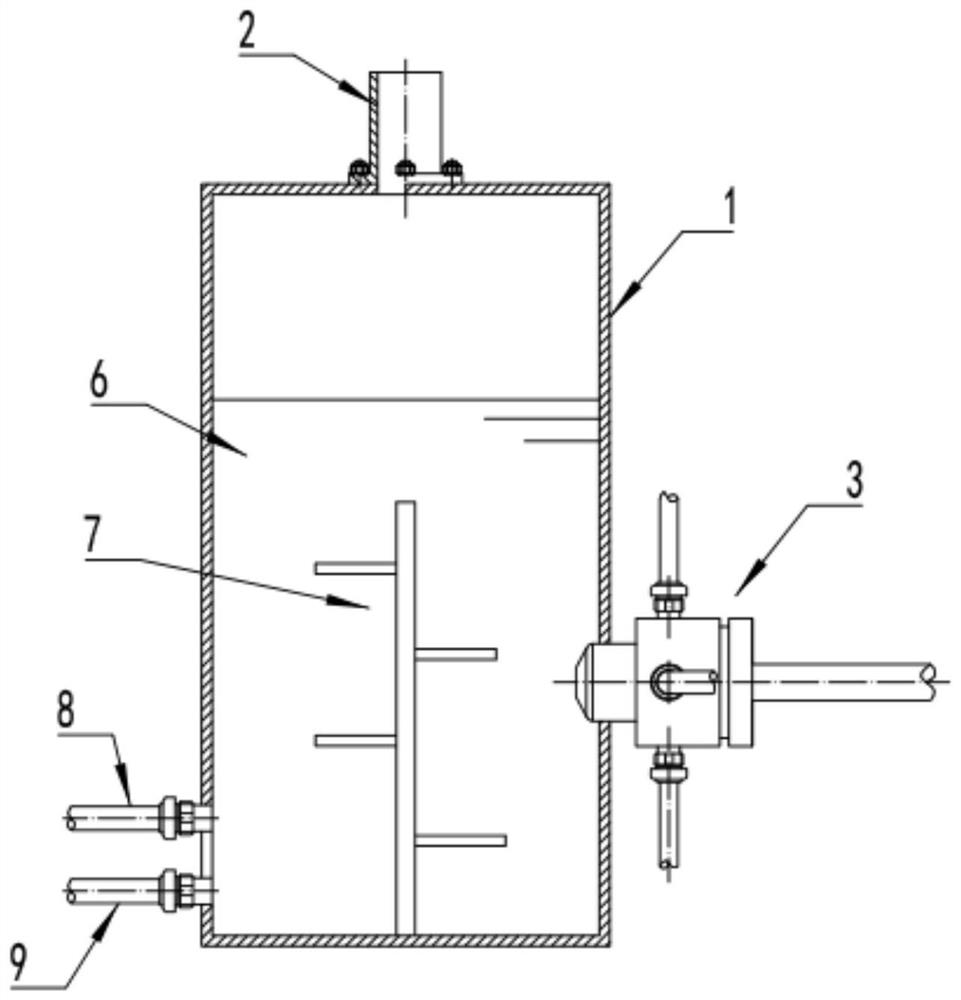
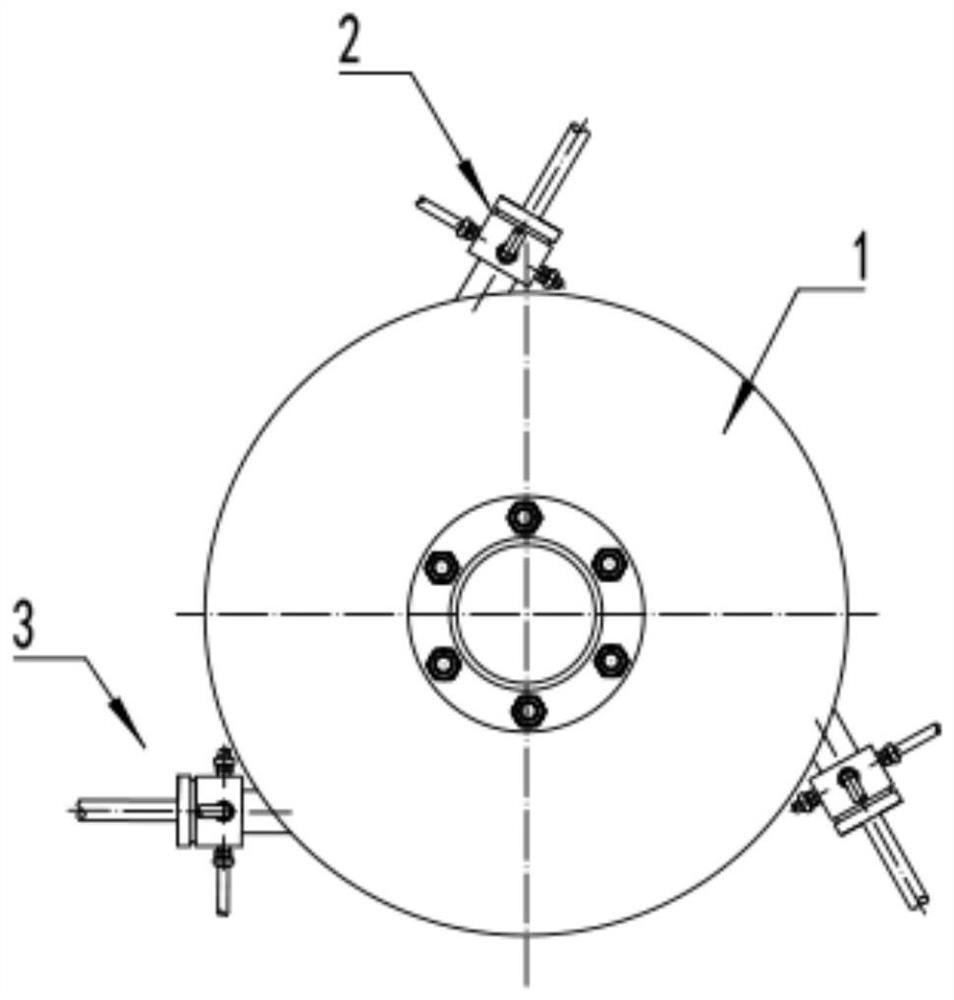
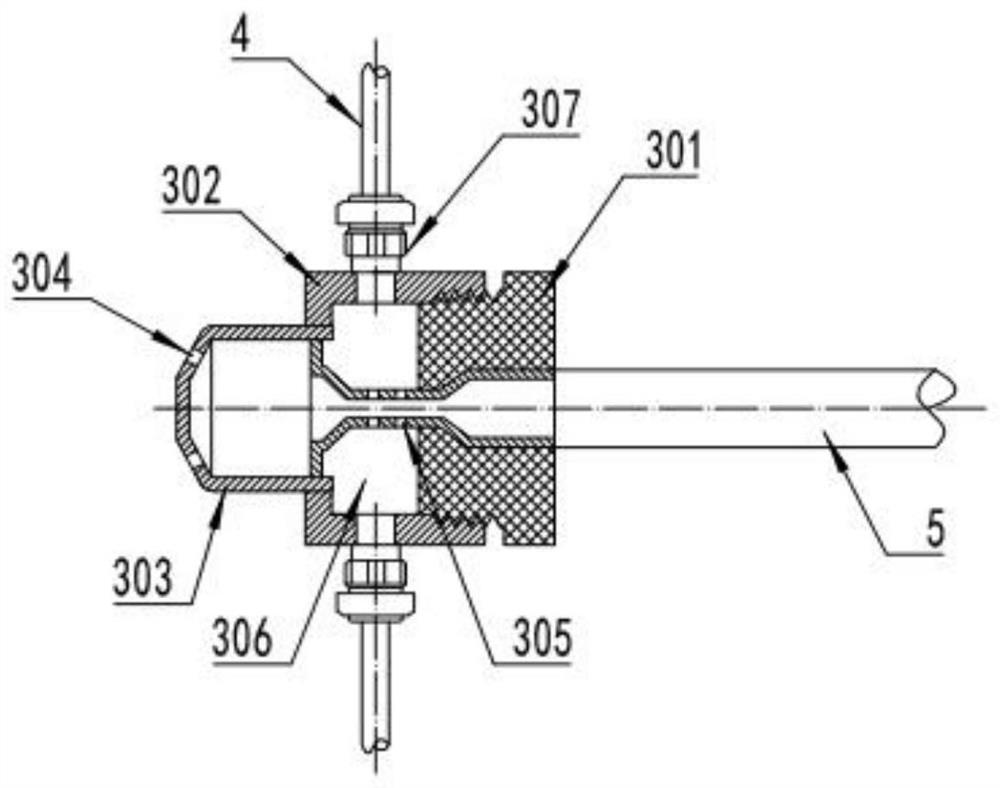
[0021] Such as Figure 1~2 Shown is a structural diagram of a high-temperature tail gas cooling device for chemical industry provided by an embodiment of the present invention, including a heat collecting oil tank 1, a low-temperature tail gas pipe 2, a mixing mechanism 3, a high-temperature tail gas pipe 4 and a Venturi tube 5, the mixing The mechanism 3 is connected to the heat collecting oil tank 1, the number of the mixing mechanism 3 is multiple, and the mu...


PUM


Abstract

The invention is applicable to the technical field of chemical production, and provides a chemical high-temperature tail gas cooling device. The chemical high-temperature tail gas cooling device comprises a heat collecting oil tank, a low-temperature tail gas pipe, a plurality of mixing mechanisms, a high-temperature tail gas pipe and a Venturi tube; the plurality of mixing mechanisms are connected with the heat collecting oil tank, the plurality of mixing mechanisms are evenly distributed in the tangential direction of the heat collecting oil tank and used for enabling mixed gas to drive cooling oil in the heat collecting oil tank to flow, the top of the heat collecting oil tank is connected with the low-temperature tail gas pipe through a flange and a sealing gasket, and a turbulent flowmechanism is further arranged in the heat collecting oil tank and used for disturbing the flowing cooling oil, so that the temperature of the cooling oil is evenly distributed. The chemical high-temperature tail gas cooling device has the beneficial effects that the chemical high-temperature tail gas cooling device is simple in overall structure, compact in arrangement and capable of being widelyused in heat recovery of high-temperature tail gas.

Description

technical field [0001] The invention relates to a heat recovery device, in particular to a high-temperature tail gas cooling device for chemical industry. Background technique [0002] Chemical tail gas refers to the poisonous and harmful gas discharged from chemical plants in chemical production. Chemical tail gas often contains many types of pollutants, complex physical and chemical properties, and different toxicity, which seriously pollutes the environment and affects human health. The composition of chemical tail gas produced by different chemical production industries varies greatly. For example, the waste gas produced by the chlor-alkali industry mainly contains chlorine, hydrogen chloride, vinyl chloride, mercury, acetylene, etc., and the waste gas produced by the nitrogen fertilizer industry mainly contains nitrogen oxides, urea dust, carbon monoxide, ammonia, sulfur dioxide, methane, etc. [0003] Part of the chemical tail gas has high temperature, if it is direc...

Claims


Application Information

Patent Timeline
IPC IPC(8): F28C3/06F28F25/02F28F9/24
CPCF28C3/06F28F9/24F28F25/02
Inventor 马留芳
Owner 马留芳
Learn More