Method, device, and air conditioner for determining correspondence between temperature sensors

A temperature sensor and corresponding relationship technology, which is applied in the direction of control input, application, heating mode, etc. related to air characteristics, can solve problems such as dismantling and maintenance, affecting the operation effect of air conditioners, and achieve the effect of avoiding dismantling and maintenance

Active Publication Date: 2021-08-24
NINGBO AUX ELECTRIC +1
View PDF0 Cites 0 Cited by
  • Summary
  • Abstract
  • Description
  • Claims
  • Application Information

AI Technical Summary

Problems solved by technology

The liquid pipe temperature sensor is used to detect the temperature of the liquid pipe of the internal machine, the middle pipe temperature sensor is used to detect the temperature of the evaporator in the internal machine, and the air pipe temperature sensor is used to detect the temperature of the air pipe of the internal machine. Therefore, the liquid pipe temperature sensor, the middle pipe temperature The installation positions of the sensor and the air pipe temperature sensor are very close, and for the liquid pipe temperature sensor, the middle pipe temperature sensor and the air pipe temperature sensor itself, the shape and color of each temperature sensor are also very similar. Therefore, in the air conditioner assembly process , it is very easy to connect the liquid pipe temperature sensor, the middle pipe temperature sensor and the air pipe temperature sensor wrongly, which will affect the operation effect of the air conditioner
After the temperature sensor is wrongly connected, it usually needs to be disassembled for maintenance

Method used


Image

  • Method, device, and air conditioner for determining correspondence between temperature sensors
  • Method, device, and air conditioner for determining correspondence between temperature sensors
  • Method, device, and air conditioner for determining correspondence between temperature sensors

Examples


Embodiment Construction

[0061] In order to make the above objects, features and advantages of the present invention more comprehensible, specific embodiments of the present invention will be described in detail below in conjunction with the accompanying drawings.

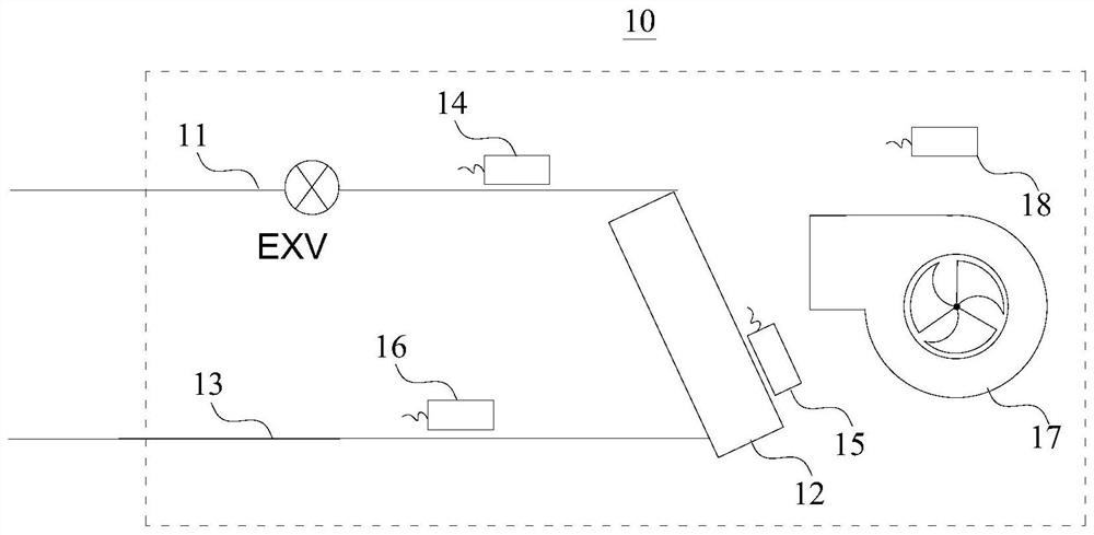
[0062] In the air conditioner 100 , the liquid pipe temperature sensor 14 , the middle pipe temperature sensor 15 , the gas pipe temperature sensor 16 and the ambient temperature sensor 18 are ubiquitous. like figure 1 As shown, the liquid pipe temperature sensor 14 is used to detect the temperature of the liquid pipe 11 in the internal machine, the middle pipe temperature sensor 15 is used to detect the temperature of the evaporator in the internal machine, and the air pipe temperature sensor 16 is used to detect the temperature of the air pipe 13 in the internal machine. The ambient temperature sensor 18 is used to detect the temperature in the environment where the indoor unit is located. Therefore, when the temperature sensor is connec...


PUM


Abstract

The present invention provides a method and device for determining the corresponding relationship of temperature sensors, and an air conditioner. The air conditioner includes a plurality of internal units, each of which includes a plurality of temperature sensors, and the plurality of temperature sensors are respectively arranged on the liquid pipe, the middle pipe and the gas pipe. A plurality of temperature sensors include a liquid pipe temperature sensor, a medium pipe temperature sensor, and an air pipe temperature sensor. The method is applied to an air conditioner, and the method includes controlling the air conditioner to operate in a cooling mode; The temperature collected by each temperature sensor; according to the temperature collected by the liquid pipe temperature sensor and gas pipe temperature sensor of the indoor unit, the ambient temperature of the indoor unit, the low pressure saturation temperature in the middle pipe, the opening degree of the expansion valve of the internal unit and the internal temperature of the air conditioner The temperature collected by the middle pipe temperature sensor of the machine and other internal machines is used to determine the temperature sensors corresponding to the liquid pipe, the gas pipe and the middle pipe respectively from a plurality of temperature sensors. The solution of the embodiment of the present application can determine the temperature sensors of the air conditioner corresponding to the liquid pipe, the air pipe, and the middle pipe respectively.

Description

technical field [0001] The present invention relates to the technical field of air-conditioning control, in particular to a method and device for determining the corresponding relationship of temperature sensors, and an air-conditioner. Background technique [0002] In air conditioners, there are liquid pipe temperature sensors, middle pipe temperature sensors, gas pipe temperature sensors and ambient temperature sensors. The liquid pipe temperature sensor is used to detect the temperature of the liquid pipe of the internal machine, the middle pipe temperature sensor is used to detect the temperature of the evaporator in the internal machine, and the air pipe temperature sensor is used to detect the temperature of the air pipe of the internal machine. Therefore, the liquid pipe temperature sensor, the middle pipe temperature The installation positions of the sensor and the air pipe temperature sensor are very close, and for the liquid pipe temperature sensor, the middle pipe...

Claims


Application Information

Patent Timeline
Patent Type & Authority Patents(China)
IPC IPC(8): F24F11/30F24F11/64F24F11/89F24F110/10F24F140/12F24F140/20
CPCF24F11/30F24F11/64F24F11/89F24F2110/10F24F2140/12F24F2140/20
Inventor 刘永超张稳刘合心程相欣
Owner NINGBO AUX ELECTRIC
Why Eureka
Try Eureka