
Antenna mast lifting speed reducer gear shifting mechanism

A shifting mechanism and reducer technology, applied in the direction of controlled components, mechanical equipment, mechanical control devices, etc., can solve the problems of difficult processing, poor shifting experience, low transmission efficiency, etc., to achieve convenient shifting operation, processing Convenience, simple structure and reliable effect

Pending Publication Date: 2020-11-13
WANSHSIN SEIKOU HUNAN CO LTD
View PDF0 Cites 2 Cited by
  • Summary
  • Abstract
  • Description
  • Claims
  • Application Information

AI Technical Summary

Problems solved by technology

The antenna mast lifting reducer on the market adopts a worm gear mechanism, which is difficult to process and has low transmission efficiency. The motor power needs to be selected large
The shifting mechanism uses a rack and pinion to move the shifting gear, and the shifting experience is poor

Method used


Image

  • Antenna mast lifting speed reducer gear shifting mechanism
  • Antenna mast lifting speed reducer gear shifting mechanism
  • Antenna mast lifting speed reducer gear shifting mechanism

Examples


Embodiment Construction

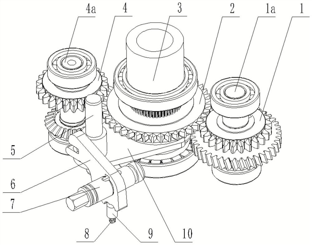
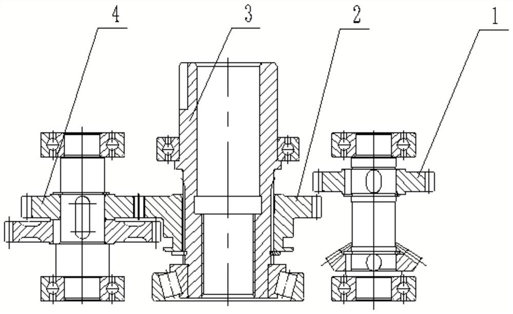
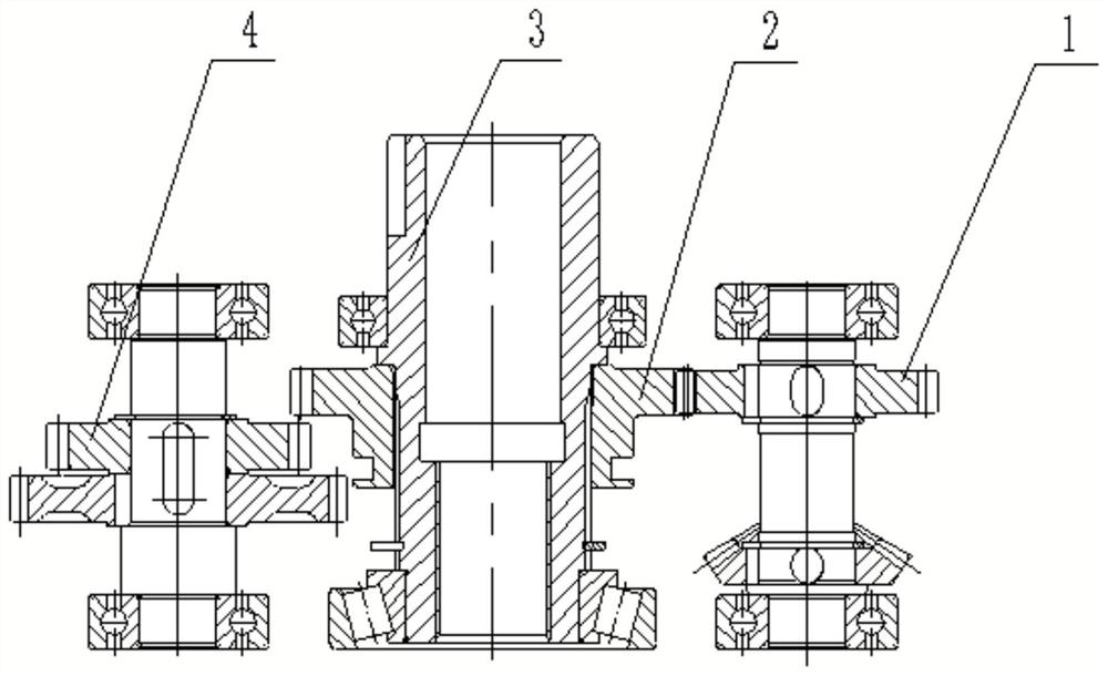
[0020] like Figure 1-4 The shifting mechanism of antenna mast lifting reducer shown includes an output shaft 3, and the parallel output shaft 3 is equipped with an electric input shaft 1a and a manual input shaft 4a; the output shaft 3 is slidingly engaged with a shift gear 2; the electric input shaft The electric end gear 1 is fixed on 1a; the manual end gear 4 is fixed on the manual input shaft 4a; the electric end gear 1 and the manual end gear 4 are in different planes; the shift gear 2 is fixedly connected with a shift mechanism; The gear mechanism includes a shift fork 10 fixedly connected with the shift gear 2, and the shift fork 10 is connected with a cam rotation mechanism.

[0021] The cam rotation mechanism comprises a shift fork pin 10a fixedly connected with the shift fork 10, and the shift fork pin 10a is slidably connected with a cam shift block 6, and the cam shift block 6 is formed with an opening groove 6b matched with the shift fork pin 10a; the cam shift b...


PUM


Abstract

The invention discloses an antenna mast lifting speed reducer gear shifting mechanism. The antenna mast lifting speed reducer gear shifting mechanism comprises an output shaft, an electric input shaftand a manual input shaft, wherein the electric input shaft and the manual input shaft are arranged in parallel to the output shaft. The output shaft is in sliding and engaged connection with a shifting gear. An electric end gear is fixed to the electric input shaft. A manual end gear is fixed to the manual input shaft. The electric end gear and the manual end gear are located in different planes.The shifting gear is fixedly connected with a gear shifting mechanism. The gear shifting mechanism comprises a shifting fork fixedly connected with the shifting gear. The shifting fork is connected with a cam rotating mechanism. The antenna mast lifting speed reducer gear shifting mechanism is convenient to machine, fast and convenient to operate during gear shifting and simple and reliable in structure, and can conveniently switch power sources for lifting an antenna mast as required.

Description

Technical field: [0001] The invention belongs to the field of machinery, in particular to a shift mechanism for an antenna mast lifting reducer. Background technique: [0002] The reducer is a power transmission mechanism that uses the speed conversion of the gear to reduce the speed of the motor to the required speed and obtain a larger torque device. The reducer has a large transmission ratio, a large output torque, and a low speed. , stable transmission, low noise, high output rigidity and so on. It has been widely used in various industries. [0003] The military antenna mast lifting reducer is used for the field antenna lifting of the troops, and is used to send and receive information. When the vehicle has power, the motor can be used as power to raise and lower the antenna mast; when there is no power, switch to manual gear and use the hand crank to raise and lower the antenna mast. The antenna mast lifting reducer on the market adopts a worm gear mechanism, which ...

Claims


Application Information

Patent Timeline
Patent Type & Authority Applications(China)
IPC IPC(8): F16H3/20F16H57/023F16H63/32
CPCF16H3/20F16H57/023F16H63/32
Inventor 周清泉李永建
Owner WANSHSIN SEIKOU HUNAN CO LTD
Learn More