
A rotary micro-injection mold with in-mold assembly function

An injection mold and in-mold assembly technology, which is applied in the field of rotary micro-injection molds, can solve the difficulty in balancing large plasticization amount and small precision mold filling amount, cannot achieve large-scale promotion, mass production, and increase the processing cost of plastic parts. Difficulty and other problems, to achieve the effect of simple structure, improve production efficiency and reduce energy consumption

Active Publication Date: 2022-05-13
拓凌机械(浙江)有限公司
View PDF5 Cites 0 Cited by
  • Summary
  • Abstract
  • Description
  • Claims
  • Application Information

AI Technical Summary

Problems solved by technology

But so far, my country's micro-injection molding machines and micro-plastic products are basically dependent on imports, and domestic research on micro-injection molding machines is still in imitation or transformation. , the green energy saving of the system, or the production efficiency and product diversity of micro-plastic parts, there is still a big gap with imported micro-injection molding machines
[0003] At present, there are two main problems faced by the injection molding process of micro-products: 1) The force balance of the mold is complicated during the mold-clamping process of micro-injection molding. Well, it is difficult to balance the large amount of plasticization and small precision mold filling; 2) Micro-injection parts require high precision, and for some micro-injection parts that require assembly and secondary processing, especially micro-injection molding with hollow structures Parts, conventional injection molding methods are difficult to produce, and it is difficult to meet the proposed assembly accuracy requirements. To meet the requirements often requires extremely high costs, and it is impossible to achieve large-scale promotion and mass production
The domestic in-mold assembly technology has just started. The current in-mold assembly technology often needs to go through complex mold structures, such as the cooperation of inserts, sliders, gears, etc., and often requires two or more injection processes. These have greatly improved The processing cost and difficulty of plastic parts make this technology unable to be popularized and applied on a large scale

Method used


Image

  • A rotary micro-injection mold with in-mold assembly function
  • A rotary micro-injection mold with in-mold assembly function
  • A rotary micro-injection mold with in-mold assembly function

Examples


Embodiment Construction

[0036] The present invention will be described in detail below with reference to the accompanying drawings and preferred embodiments, and the purpose and effect of the present invention will become clearer. It should be understood that the specific embodiments described here are only used to explain the present invention and are not intended to limit the present invention.

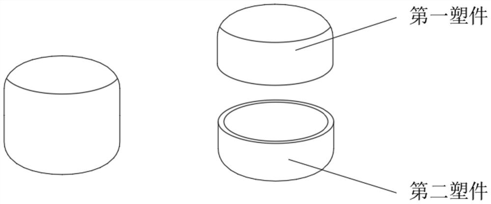
[0037] The rotary micro-injection mold with in-mold assembly function of the present invention is used for molding such as figure 1 The shown microplastic parts contain hollow structures, and their structure dimensions are on the order of millimeters. In the specific injection molding process of this mold, the first plastic part and the second plastic part will be injected separately, and finally the final plastic part will be obtained by in-mold assembly.

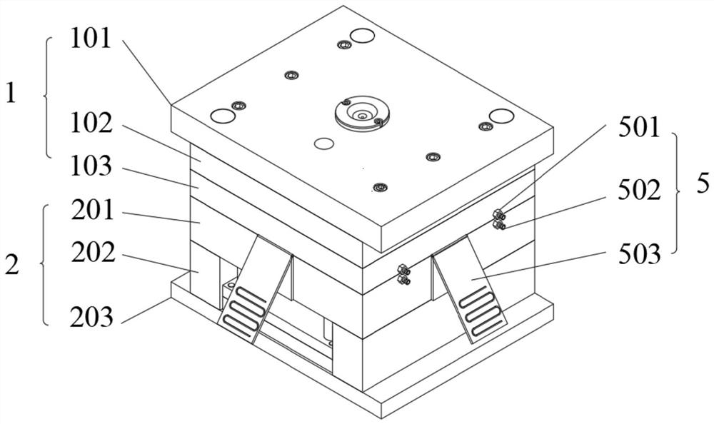
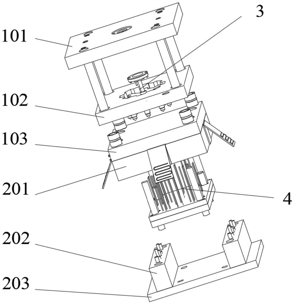
[0038] Such as figure 2 As shown in -7, the rotary micro-injection mold with in-mold assembly function of the present invention includes a fixed mol...


PUM


Abstract

The invention discloses a rotary micro-injection mold with an in-mold assembly function, belonging to the technical field of micro-injection molds. The micro-injection mold includes a fixed mold assembly, a movable mold assembly, a pouring assembly, a demoulding assembly, a temperature adjustment system, and a core positioning mechanism. The invention applies the in-mold assembly technology to the micro-injection mold, solves the difficult problem of processing and assembling micro-plastic parts with hollow structures, and realizes efficient, accurate and batch production.

Description

technical field [0001] The invention relates to the field of micro-injection molds, in particular to a rotary micro-injection mold with an in-mold assembly function. Background technique [0002] Micro-injection molding refers to an injection molding method used to form plastic products with a size of microns and a quality of milligrams. In recent years, the demand for plastic micro-products in various micro-electromechanical systems (MEMS) products such as micro-drivers, micro-sensors, micro-robots, and micro-satellites has increased. But so far, my country's micro-injection molding machines and micro-plastic products are basically dependent on imports, and domestic research on micro-injection molding machines is still in imitation or transformation. , The green energy saving of the system, or the production efficiency and product diversity of micro-plastic parts, there is still a big gap with imported micro-injection molding machines. [0003] At present, there are two ma...

Claims


Application Information

Patent Timeline
Patent Type & Authority Patents(China)
IPC IPC(8): B29C45/26B29C45/33B29C45/36B29C45/73
CPCB29C45/26B29C45/33B29C45/36B29C45/73
Inventor 许方敏许忠斌徐宁涛邵文良邵晨顾敏
Owner 拓凌机械(浙江)有限公司
Learn More