
Tool for assembling driving motor and speed reducer

A technology for driving motors and reducers, which can be used in metal processing, manufacturing tools, workpiece clamping devices, etc., and can solve the problem of damage to the positioning accuracy of the drive motor and reducer, extrusion deformation, spline mating noise, etc. problems, to achieve the effect of convenient assembly operation, avoiding radial force, and ensuring meshing accuracy

Active Publication Date: 2020-11-13
HEFEI JUYI POWER SYST CO LTD
View PDF10 Cites 1 Cited by
  • Summary
  • Abstract
  • Description
  • Claims
  • Application Information

AI Technical Summary

Problems solved by technology

[0003] At present, due to the high machining accuracy of the spline mating pair of the driving motor and the reducer, it is difficult to accurately center the spline mating pair and mesh synchronously during the assembly process, so it is difficult to achieve fully automated assembly, and still needs the assistance of the operator Complete the cog meshing between the spline shaft of the drive motor and the spline sleeve of the reducer before assembly
At present, the drive motor and reducer shells are mostly made of lightweight die-casting aluminum alloy. Although the drive motor and reducer are assembled using a reliable six-point positioning method, there is a reasonable gap between each positioning fit, and the other is due to the aluminum alloy. The material is soft, and it is prone to defects such as extrusion and deformation during assembly, which damages the positioning accuracy of the drive motor and reducer, which in turn affects the positioning accuracy of the drive motor and reducer spline matching pair, resulting in the drive motor and reducer. The spline mating pair of the motor is subjected to additional radial force, and the spline mating pair meshing noise occurs during the high-speed operation of the electric drive system, which affects the service life of the spline mating pair

Method used


Image

  • Tool for assembling driving motor and speed reducer
  • Tool for assembling driving motor and speed reducer
  • Tool for assembling driving motor and speed reducer

Examples


Embodiment

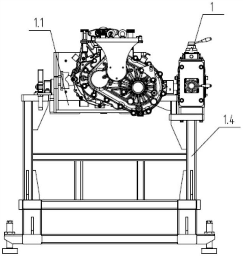
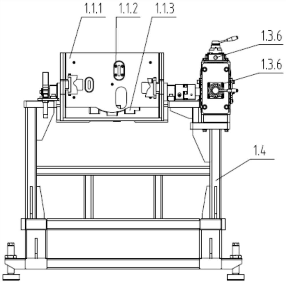
[0033] Embodiment: This application provides a drive motor and reducer combined tooling, combined with reference Figure 1 to Figure 9 , The drive motor and reducer assembly tooling includes: drive motor overturn trolley 1, drive motor assembly positioning plate 3, reducer spreader 4, spline shaft hook wrench 6.

[0034] The drive motor overturn trolley 1 realizes the overturn of the drive motor 2 in the horizontal or vertical direction of the spline shaft. The drive motor overturn trolley 1 is equipped with a drive motor positioning mechanism, a pneumatic clamping mechanism, a pneumatic overturn mechanism, and a supporting steel frame structure; the drive motor positioning The mechanism is used to locate and install the drive motor 2, the pneumatic clamping mechanism is used to clamp the drive motor 2, the pneumatic turning mechanism is used to realize the turning and positioning of the drive motor 2 during the assembly process, and the supporting steel frame structure is used...


PUM


Abstract

The invention discloses a tool for assembling a driving motor and a speed reducer. The tool comprises a driving motor turnover trolley, a driving motor combined assembly positioning plate, a speed reducer lifting appliance and a spline shaft hook wrench. Manual intervention is adopted for confirmation, the problem that a spline matching pair of the driving motor and the speed reducer is difficultto accurately center and synchronously mesh in place in the assembling process is solved, the driving motor turnover trolley is adopted, the spline matching pair of the driving motor and the speed reducer is preassembled in the vertical state and locked in the horizontal state, assembling operation of an operator is facilitated, meanwhile, extra radial acting force generated in the assembling process of a spline shaft of the driving motor and a spline sleeve of the speed reducer is avoided, and the meshing precision of the spline shaft of the driving motor and the spline sleeve of the speed reducer under the mass production condition is ensured.

Description

technical field [0001] The invention belongs to the field of combined assembly of a driving single machine and a reducer, and relates to a combined assembly tooling of a driving motor and a reducer. Background technique [0002] The combination of drive motor and reducer is an important process in the assembly process of the electric drive system of new energy vehicles. It is to ensure the meshing accuracy of the spline shaft of the drive motor and the spline sleeve of the reducer under mass production conditions, and to reduce the meshing of spline mating pairs. Noise, prolong the service life of the spline mating pair. [0003] At present, due to the high machining accuracy of the spline mating pair of the driving motor and the reducer, it is difficult to accurately center and synchronously mesh the spline mating pair during the assembly process, so it is difficult to achieve fully automated assembly, and still requires the assistance of the operator Complete the cog mesh...

Claims


Application Information

Patent Timeline
Patent Type & Authority Applications(China)
IPC IPC(8): B23P19/027B23P19/10B25B11/02
CPCB23P19/027B23P19/10B25B11/02
Inventor 刘蕾凌志孙原王文志张来平
Owner HEFEI JUYI POWER SYST CO LTD
Learn More