
Clutch

A clutch and meshing pair technology, applied in the field of clutches, can solve the problems affecting the performance of the clutch, the failure of the outer spline of the center sleeve, and the short length of the positioning guide, so as to improve the comfort and commerciality, increase the service life, and combine fast. Effect

Inactive Publication Date: 2020-11-10
LONCIN MOTOR +1
View PDF9 Cites 1 Cited by
  • Summary
  • Abstract
  • Description
  • Claims
  • Application Information

AI Technical Summary

Problems solved by technology

[0004] In the prior art, there will be relative axial movement between the pressure plate and the clutch during the engagement and disengagement process. This axial movement is expected to have better stability, so a radial positioning axial movement is required between the pressure plate and the center sleeve. The guide structure, while the basic structure of the existing clutch positioning guide is the positioning of the center hole of the pressure plate and the boss of the power transmission journal (inner spline) of the center sleeve. This structure is limited by the space. The positioning guide length is relatively short. The positioning and guiding parts are short and easy to twist, which will easily cause vibration and instability, which will affect the performance of the clutch
[0005] At the same time, due to the limited space of the vehicle engine, the volume of the clutch is limited, so the transmitted torque is limited. If a larger torque needs to be transmitted, the installation space must be expanded or the force value of the main spring of the clutch should be increased to increase the reserve coefficient of the clutch, resulting in clutch manipulation. The force value is getting bigger and bigger, especially for motorcycles, manual control is required, and a large control force is required. In order to ensure smooth and simple manual control, the clutch needs to have a small spring reserve coefficient. There is a contradiction between the two ;At the same time, when the clutch transmits power, the external splines of the center sleeve are passively stressed. When the transmission torque is large, the strength of the external splines of the center sleeve is required to be high. Long-term large torque transmission will cause insufficient torque matching and cause the center sleeve The external spline fails; the clutch of the prior art has a long sliding time when engaging, and ablation occurs between the friction plates, and in practice, ablation accounts for the vast majority of clutch failures;

Method used


Image

  • Clutch
  • Clutch
  • Clutch

Examples


Embodiment Construction

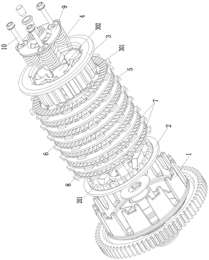
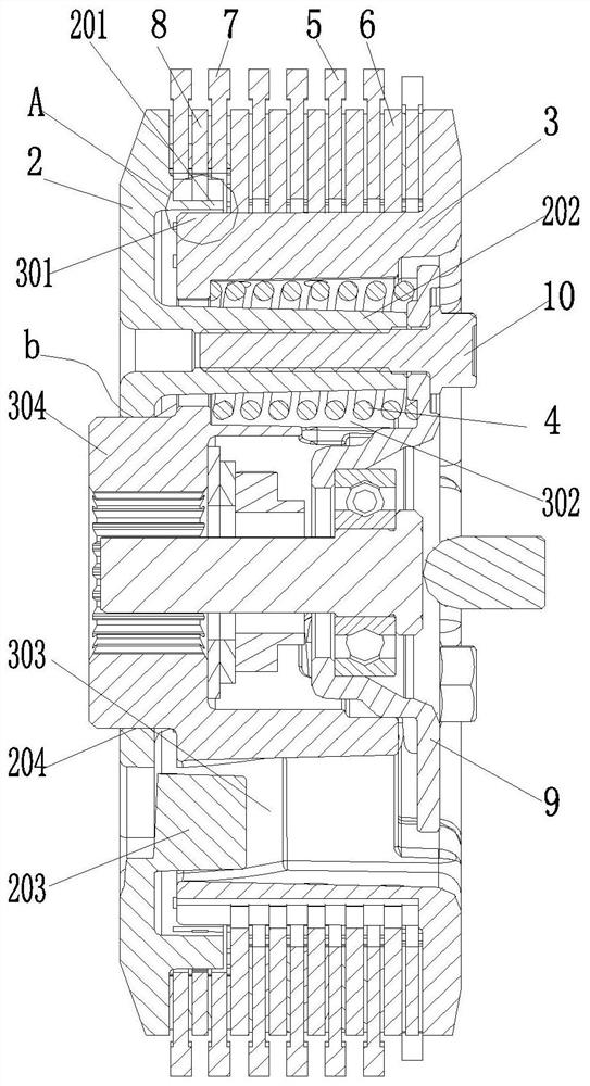
[0037] As shown in the figure, the clutch of this embodiment includes a pressure plate 2, a friction plate assembly and a center sleeve 3;

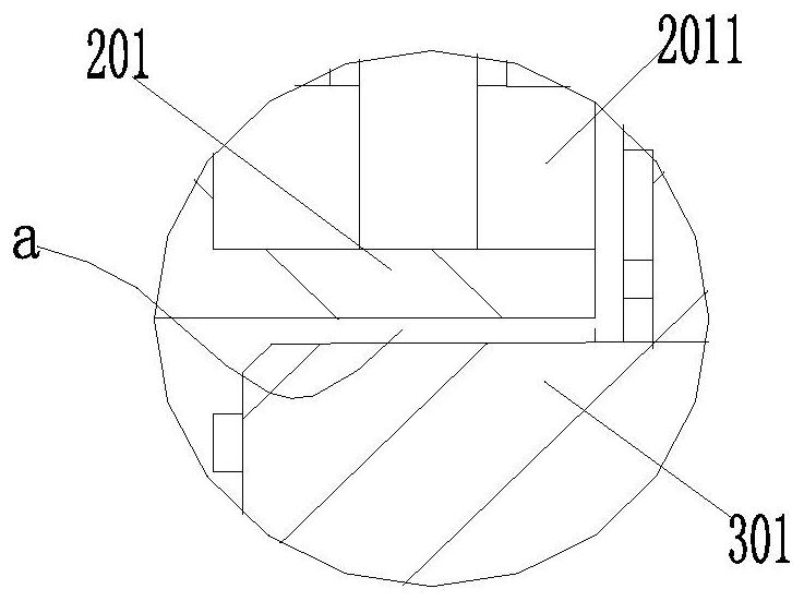
[0038] The pressure plate 1 is provided with a positioning guide part that cooperates with the center sleeve 3 in the vicinity of the center sleeve outer spline 301 to form radial positioning and axial guidance, and the positioning guide part and the center sleeve 3 form a positioning guide structure a;

[0039] The engagement between the pressing plate and the center sleeve is also formed through the helical tooth engagement pair on the end face;

[0040] The structure of the clutch certainly includes parts such as outer cover 1, pressure plate 2, center sleeve 3, lifting plate 9, main spring 4, friction plate assembly (active friction plate 5 is arranged on outer cover 1, driven friction plate 6 is arranged on center sleeve 3), and pressure plate 2 or the center sleeve 3 is provided with a spring seat sinking groove for accommodating th...


PUM


Abstract

The invention discloses a clutch. The clutch comprises a pressing plate, a friction plate assembly and a central sleeve. The pressing plate is provided with a positioning guide part in radial positioning and axial guide fit with the central sleeve near an external spline of the central sleeve; and the pressing plate is meshed with the central sleeve through a bevel meshing pair. According to the clutch, the centering precision of the clutch is improved, vibration generated when the clutch is combined and separated is reduced, and the control stability of the clutch is guaranteed; meanwhile, the central sleeve and the pressing plate are associated through the bevel meshing pair, and when set relative rotation occurs, the bevel meshing pair can increase the output torque of the clutch and increase the reserve coefficient of the clutch, so that the force transmission capacity is improved, the sliding abrasion time of the clutch is shortened, and fault ablation is avoided; and a positioning guide mechanism can enable the alignment of the bevel meshing pair, meshing and pressing processes are smooth, and vibration, clamping stagnation and ablation of the clutch in the jointing process can be helpfully avoided, so that the service life of the clutch can be helpfully prolonged, and the overall performance of the clutch can be improved.

Description

technical field [0001] The present invention relates to engine components or accessory components, in particular to a clutch. Background technique [0002] The clutch is located between the engine and the gearbox. It is a component in the transmission system that is directly connected to the engine. It is a transmission mechanism used to transmit or cut off power between the engine and the gearbox. [0003] The clutch includes a pressure plate, a center sleeve combination with a driven friction plate, an elastic component, a lifting plate, and an outer cover combination with an active friction plate; The driven friction plate on the center sleeve and the active friction plate combined by the outer cover are tightly attached to form a transmission. When separation is required, the lifting plate is driven by an external force to compress the elastic component to drive the pressure plate and the center sleeve to separate, so that the active friction plate It is separated from ...

Claims


Application Information

Patent Timeline
Patent Type & Authority Applications(China)
IPC IPC(8): F16D13/52F16D13/72F16D13/58F02B61/06
CPCF02B61/06F16D13/52F16D13/58F16D13/72
Inventor 凌磊蒋博文周良兵彭发碧阳远贵
Owner LONCIN MOTOR
Learn More