
Bearing pedestal structure with cooling inner runner for turbine pump

A bearing seat and inner flow channel technology, applied in bearing cooling, bearing components, shafts and bearings, etc., can solve the problems of reducing bearing seat support stiffness, turbo pump resonance, insufficient critical speed margin of turbo pump, etc., to improve the critical speed. effect of rotational speed, increased reliability, reduced risk of excess

Active Publication Date: 2020-11-10
XIAN AEROSPACE PROPULSION INST
View PDF14 Cites 1 Cited by
  • Summary
  • Abstract
  • Description
  • Claims
  • Application Information

AI Technical Summary

Problems solved by technology

However, since part of the flow channel is located above the bearing, this design will reduce the support rigidity of the bearing seat, resulting in insufficient critical speed margin of the turbo pump, resulting in the risk of resonance in the turbo pump

Method used


Image

  • Bearing pedestal structure with cooling inner runner for turbine pump
  • Bearing pedestal structure with cooling inner runner for turbine pump
  • Bearing pedestal structure with cooling inner runner for turbine pump

Examples


Embodiment Construction

[0031] Exemplary embodiments of the present disclosure will be described in more detail below with reference to the accompanying drawings. Although exemplary embodiments of the present disclosure are shown in the drawings, it should be understood that the present disclosure may be embodied in various forms and should not be limited by the embodiments set forth herein. Rather, these embodiments are provided for more thorough understanding of the present disclosure and to fully convey the scope of the present disclosure to those skilled in the art. It should be noted that, in the case of no conflict, the embodiments of the present invention and the features in the embodiments can be combined with each other. The present invention will be described in detail below with reference to the accompanying drawings and examples.

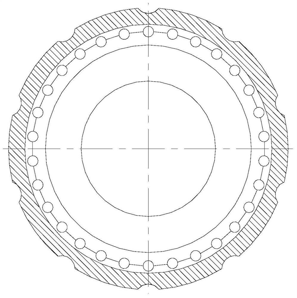
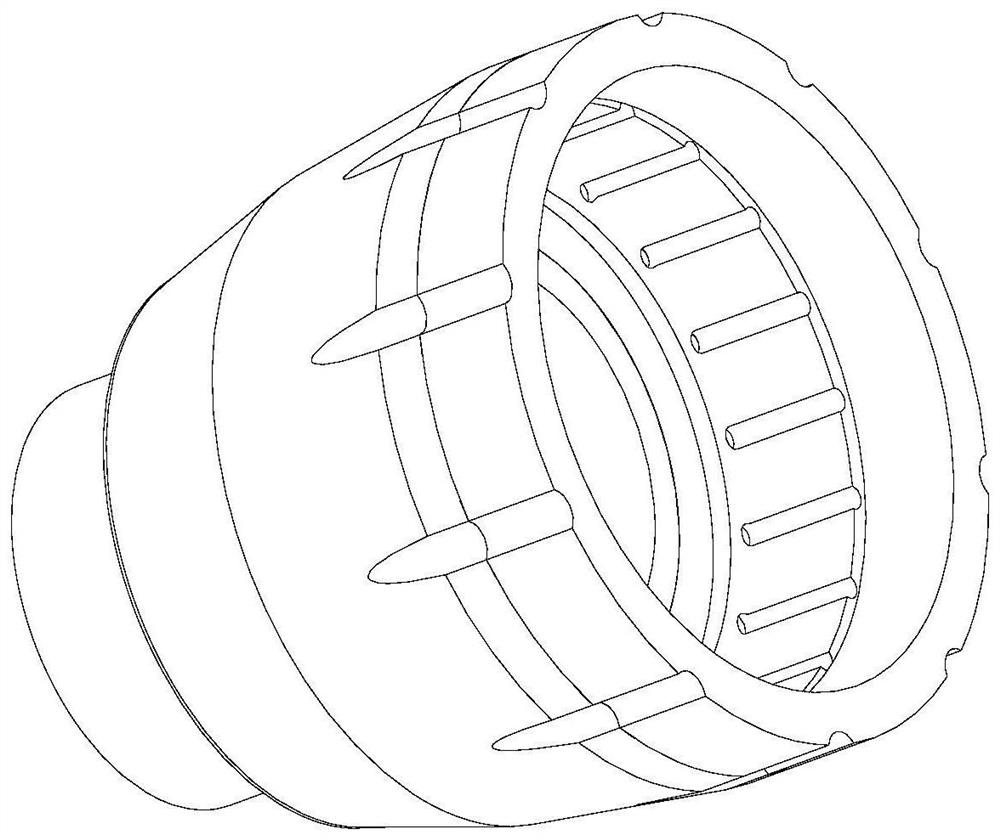
[0032] figure 1 It is a front view of a bearing seat structure with a cooling inner flow channel for a turbo pump provided by an embodiment of the present in...


PUM


Abstract

The invention discloses a bearing pedestal structure with a cooling inner runner for a turbine pump. The bearing pedestal structure comprises a bearing pedestal left section, a bushing and a bearing pedestal right section. The right end of the bearing pedestal left section is welded with the bearing pedestal right section through electron beam welding, the bushing is sleeved with the bearing pedestal left section, and the bearing pedestal left section is connected with a positioning step of the bushing. The bearing pedestal right section is of a rotary structure, the bearing pedestal right section and the bearing pedestal left section are welded through electron beam welding, and the bearing pedestal right section and the bearing pedestal left section are of a coaxial structure. The bushing is of a rotary structure, the large end of the bushing is welded to the bearing pedestal left section through electron beam welding, the bushing and the bearing pedestal left section are of a coaxial structure, and a bearing cooling medium inlet flow channel is formed in the space between the bushing and the bearing pedestal left section. While the pressure of a bearing cavity and the cooling flow of a bearing are guaranteed, the problem that the critical rotating speed margin of a turbine pump is small due to the fact that the rigidity of a bearing pedestal, with a cooling inner hole, of anengine turbine pump is low is solved.

Description

technical field [0001] The invention belongs to the field of liquid rocket engine turbopumps, in particular to a bearing seat structure with a cooling inner flow channel for the turbopump. Background technique [0002] The rocket engine turbo pump bearing seat is arranged at the turbine end, and its main function is to provide support for the bearing and provide a cooling channel for the bearing. The cooling flow comes from the centrifugal wheel and flows to the bearing through the cooling channel arranged inside the bearing seat. The bearing seat needs to provide the bearing with the largest possible support rigidity and sufficient cooling flow. If the cooling flow rate is too low, the bearing life will be shortened. At the same time, the flow channel of the bearing seat needs to ensure that the pressure in the front cavity of the bearing is greater than the pressure at the hub of the turbine disc. Otherwise, gas backflow will occur. In response to this problem, a commonly...

Claims


Application Information

Patent Timeline
Patent Type & Authority Applications(China)
IPC IPC(8): F16C35/00F16C37/00F04D29/056
CPCF16C35/00F16C37/00F04D29/0563
Inventor 金路许开富李惠敏任众李向阳张鹏飞蒋建园
Owner XIAN AEROSPACE PROPULSION INST
Learn More