


Quick Research
Generate reliable direction feasibility study reports for your R&D in just a few steps.

Technical Q&A
Discover and master advanced knowledge NOW. Basics, ideas, possibilities, all at once.

Find Solutions
As an expert in R&D theories, this can generate solutions to your technical problems instantly.

Evaluate Feasibility
Analyze your overall solution with one click, know your potential R&D risks in advance.

Monitor Landscape
Get weekly tech updates, stay abreast of the latest tech innovations and key insights.
Portable tray for medical clinical laboratory
A laboratory and portable technology, applied in the field of tray devices, can solve the problems of limited number of samples placed, inconvenient to take samples, inconvenient to move the tray, etc., to achieve the effect of convenient movement, improved sample storage capacity, and increased storage capacity
- Summary
- Abstract
- Description
- Claims
- Application Information
AI Technical Summary
Problems solved by technology
Method used
Image

Examples
Embodiment 1
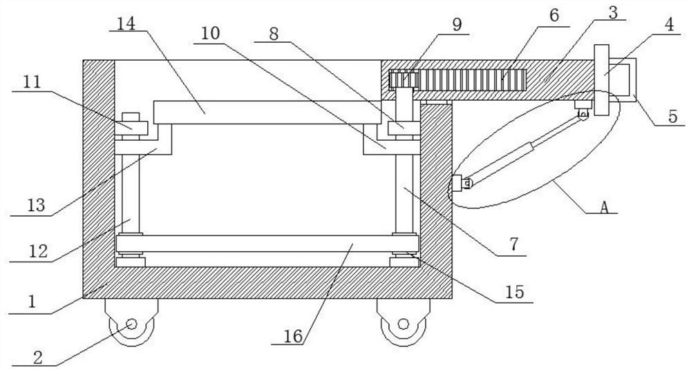
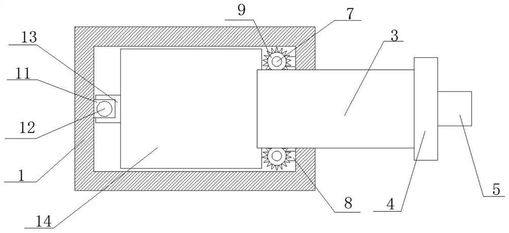
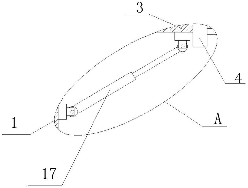
[0021] refer to Figure 1-3 , a portable tray for medical laboratory, including a box body 1, a plurality of bottom wheels 2 are fixedly installed on the bottom of the box body 1 to facilitate the movement of the whole device, a first pallet 3 is slidably installed on the top of the box body 1, and the second A connecting plate 4 is fixedly installed on one side of the supporting plate 3, and a handle 5 is fixedly installed on one side of the connecting plate 4, which is convenient for pulling the first supporting plate 3. On the inner wall of one side of the box body 1, two symmetrical rotations are installed. One screw rod 7, the bottom ends of the two first screw rods 7 are all rotatably installed on the bottom inner wall of the box body 1, the tops of the two first screw rods 7 are respectively movably connected with the two sides of the first supporting plate 3, and the two first A first support plate 10 is screw-mounted on the screw rod 7, and the two first support plate...
Embodiment 2
[0027] refer to Figure 1-3 , a portable tray for medical laboratory, including a box body 1, the bottom of the box body 1 is fixedly installed with several bottom wheels 2 by welding, which is convenient for the movement of the whole device, and the top of the box body 1 is slidably installed with a first pallet 3 One side of the first supporting plate 3 is fixedly installed with a connecting plate 4 by welding, and one side of the connecting plate 4 is fixedly installed with a handle 5 through welding, which is convenient for pulling the first supporting plate 3, and the inner wall of one side of the box body 1 is symmetrical Two first screw rods 7 are rotatably installed, and the bottom ends of the two first screw rods 7 are all rotatably installed on the bottom inner wall of the box body 1, and the top ends of the two first screw rods 7 are respectively movable with the two sides of the first supporting plate 3. connection, the two first screw rods 7 are screwed with the f...
PUM
 Abstract
Description
Claims
Application Information
 - R&D Engineer
- R&D Manager
- IP Professional
- Industry Leading Data Capabilities
- Powerful AI technology
- Patent DNA Extraction
Browse by: Latest US Patents, China's latest patents, Technical Efficacy Thesaurus, Application Domain, Technology Topic, Popular Technical Reports.
© 2024 PatSnap. All rights reserved.Legal|Privacy policy|Modern Slavery Act Transparency Statement|Sitemap|About US| Contact US: help@patsnap.com