Continuous intermittent grain particle grinding device

A grain grain, intermittent technology, applied in grain processing and other directions, can solve the problems of poor processing quality, inefficiency, low efficiency of corn grain milling equipment, etc., and achieve high work efficiency, simple structure and good effect.

Inactive Publication Date: 2020-11-10
谢秀荣
View PDF1 Cites 6 Cited by
  • Summary
  • Abstract
  • Description
  • Claims
  • Application Information

AI Technical Summary

Problems solved by technology

[0003] Chinese patent (notification number: CN 108620181 A, announcement date: 2018.10.09) discloses a kind of agricultural corn grain milling equipment, including the equipment body. The top of the equipment body is provided with two symmetrical feeding ports. The middle part of the top is fixedly connected with the first motor, which improves the working efficiency of corn grain milling equipment and solves the problem of poor processing quality
However, when crushing some similar grain particles, it is impossible to achieve the automatic input and crushing of the grain particles and the automatic output after crushing, so it cannot be solved efficiently for a large number of grain particles.

Method used


Image

  • Continuous intermittent grain particle grinding device
  • Continuous intermittent grain particle grinding device
  • Continuous intermittent grain particle grinding device

Examples


Embodiment 1

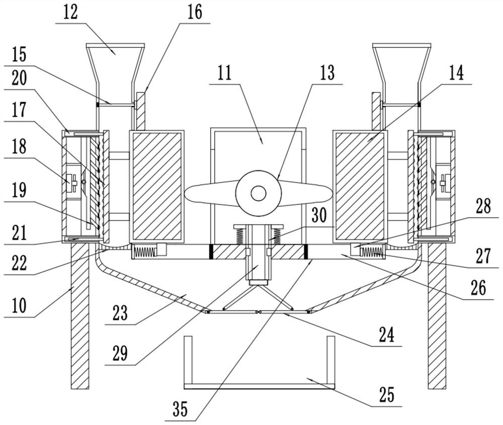
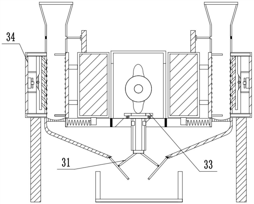
[0021] see Figure 1-3 , a continuous intermittent grain grinding device, comprising a foot 10, a feed channel 12, a material delivery channel 23, a powder collection tank 25, a bottom plate 35; A group of two-way cams 13 are arranged inside the cavity 11, and the rear center of the two-way cams 13 is rotatably connected with a rotating motor fixed on the rear side wall of the driving cavity 11. The position of the opening and closing of the chamber wall is provided with a sliding port for the end of the two-way cam 13 to pass through. There are two groups of push blocks 14 arranged symmetrically on the outside of the sliding ports on the left and right sides. In the transverse slide groove 26 inside the upper side of the base plate 35 , an anti-collision pad is fixedly installed at the inner end of the side of the transverse slide groove 26 near the center of the drive cavity 11 . The side of the slide block 28 away from the center of the drive chamber 11 is elastically conn...

Embodiment 2

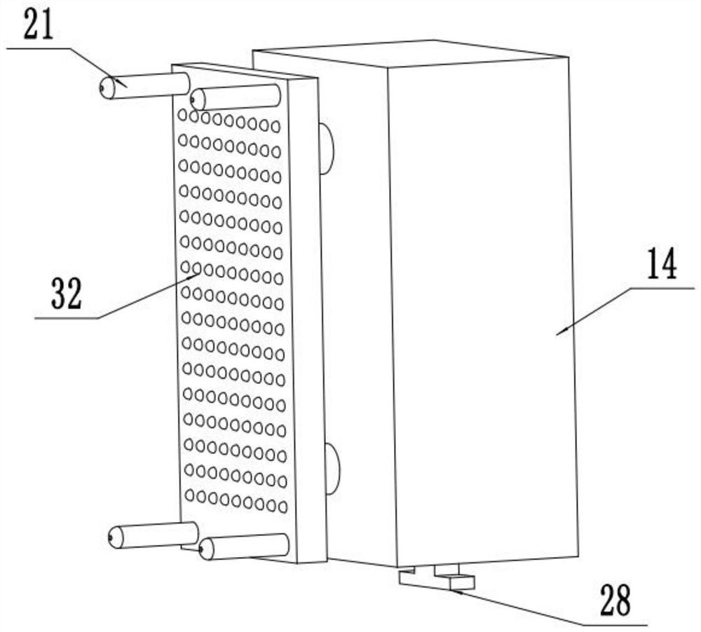
[0024] On the basis of Embodiment 1, a group of fans 18 are arranged inside the fixed rolling plate 34, and the output end of the fan 18 is connected to the side of the moving rolling plate 17 through an air pipe to the side of the fixed rolling plate 34. On the air outlet pipe 19 in the wall, the air outlet pipe 19 is set as an inclined structure that is high inside and low outside, and the air is delivered to the area between the fixed rolling plate 34 and the moving rolling plate 17 through the air outlet pipe 19, so that The powdery grain sticking to the fixed rolling plate 34 sidewall and the mobile rolling plate 17 outer wall is blown down, and the powdery grain will not enter the inside of the fixed rolling plate 34 .

[0025] The working principle of the present invention is: at first when the two-way cam 13 inside the drive cavity 11 is in the state of stopping, the fixed rolling plate 34 is in a separate state from the moving rolling plate 17, and when the grain parti...


PUM


Abstract

The invention relates to the technical field of agricultural processing equipment, and discloses a continuous intermittent grain particle grinding device which comprises supporting legs and a feedingchannel. A set of two-way cam is arranged in a driving cavity, the center of the rear side of the two-way cam is rotationally connected with a rotating motor fixed to the rear side wall of the drivingcavity, and two sets of pushing blocks are symmetrically arranged at the outer sides of sliding openings in the left side and the right side; a set of movable rolling plate parallel to the outer sidefaces of the pushing blocks is fixedly installed at each of the upper portion and the lower portion of the outer side faces of the pushing blocks through connecting rods, and a set of fixed rolling plate with the same height as the movable rolling plates and of rectangular structures are arranged at the left sides of the movable rolling plates; and the upper side of the fixed rolling plate located over a screen is fixedly communicated with the set of rectangular feeding channel with the top of a horn-shaped structure, a set of transverse movable sealing plate is fixedly installed at the topsof the pushing blocks through connecting blocks, and the bottom of the screen downwards communicates with a conveying channel with the tail end extending to the position under a bottom plate. The continuous intermittent grain particle grinding device has the advantages of continuous and automatic operation and high working efficiency.

Description

technical field [0001] The invention relates to the technical field of agricultural processing equipment, in particular to a continuous batch grain crushing device. Background technique [0002] With the development of agricultural science and technology, various grains are often ground and pulverized for subsequent processing and use after threshing in the process of production and processing, so as to facilitate better and faster subsequent use. [0003] Chinese patent (notification number: CN 108620181 A, announcement date: 2018.10.09) discloses a kind of agricultural corn grain milling equipment, including the equipment body. The top of the equipment body is provided with two symmetrical feeding ports. The middle part of the top is fixedly connected with the first motor, which improves the working efficiency of the corn grain milling equipment and solves the problem of poor processing quality. However, when some similar grain particles are crushed, the automatic input a...

Claims


Application Information

Patent Timeline
Patent Type & Authority Applications(China)
IPC IPC(8): B02C1/14B02C11/00B02C11/04
CPCB02C1/14B02C11/00B02C11/04
Inventor 谢秀荣
Owner 谢秀荣
Why Eureka
Try Eureka