Quick cutting and distributing device for food of farm livestock
A livestock and fast technology, applied in food science, transportation and packaging, feed, etc., can solve the problems of labor cost, time-consuming, labor-intensive, hand injury, etc., and achieve the effect of improving work efficiency
- Summary
- Abstract
- Description
- Claims
- Application Information
AI Technical Summary
Problems solved by technology
Method used
Image
Examples
Embodiment 1
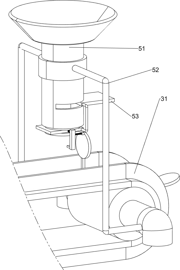
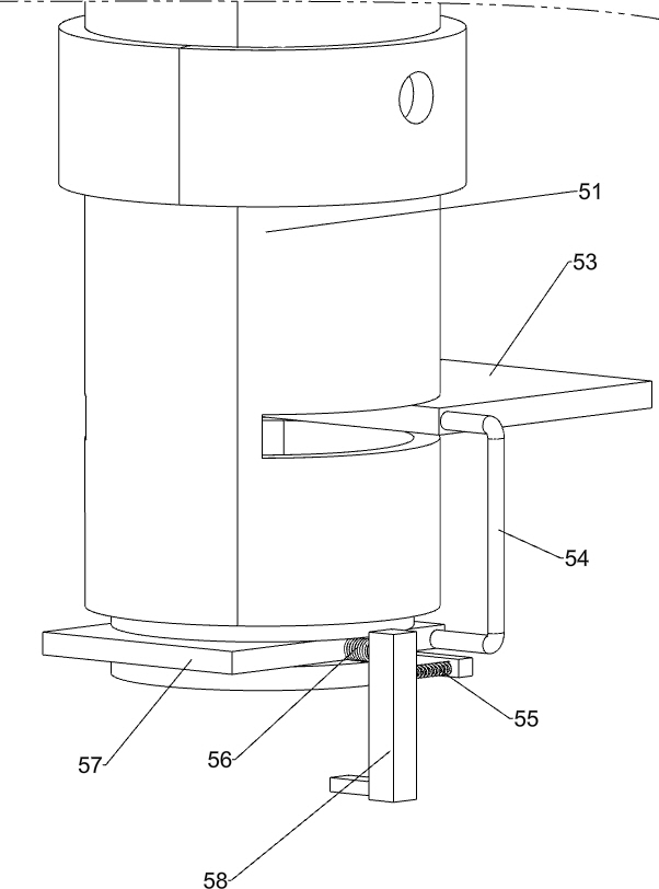
[0049] A fast cutting and matching device for farm livestock, such as figure 1 As shown, it includes a supporting column 1, a motor 2, a conveying skin cutting mechanism 3, a pushing extrusion slicing mechanism 4 and a blanking mechanism 5, the front top of the supporting column 1 is connected with the motor 2, and the rear side of the supporting column 1 is connected with a conveying cutting mechanism. Leather mechanism 3, a push extrusion slicing mechanism 4 is connected between the left side of the support column 1 and the output shaft of the motor 2, and a blanking mechanism 5 is connected to the right side of the support column 1, and the blanking mechanism 5 is squeezed and matched with the conveying skin cutting mechanism 3 .
[0050] When people need to cut and match the food, the prepared collection frame is placed on the lower left side of the device, then the washed food is poured into the feeding mechanism 5, the motor 2 is started, and the output shaft of the moto...
Embodiment 2
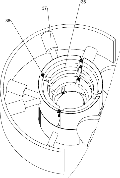
[0052] On the basis of Example 1, such as Figure 2-3 As shown, the transmission and peeling mechanism 3 includes a peeling pusher 32, a half gear 33, a spur gear 34, a transmission roller 35, a blade 36, a telescopic column 37 and a first spring 38, and the left and right sides of the support column 1 are connected in a rotational manner. There are transmission rollers 35, and there is a belt blocking type conveyor belt 31 around between the transmission rollers 35, and the belt blocking type conveyor belt 31 is evenly provided with a peeling and pushing board 32, and the peeling and pushing board 32 is squeezed and matched with parts of the blanking mechanism 5, left The front part of the transmission roller 35 on the side is connected with a spur gear 34, the output shaft of the motor 2 is connected with a half gear 33, the half gear 33 meshes with the spur gear 34, and the left side of the support column 1 is provided with a half-cylindrical barrel, which is evenly connecte...
Embodiment 3
[0055] On the basis of Example 2, such as Figure 4-6As shown, the push extrusion slicing mechanism 4 includes a flat belt combination 41, a rotating wheel 42, a driving device 43, a fixed column 44, a push-pull rod 45 and a box 46. Below the cylindrical barrel, a fixed column 44 is connected to the left front of the box 46, and a push-pull rod 45 is slidably connected between the fixed column 44 and the left side of the box 46, and an extrusion block is slidably connected in the box 46, and the left side of the extrusion block is Connect with the push-pull rod 45 right-hand sides, between the left side of fixed column 44 and the right side of box 46 front parts, sliding type is connected with driving device 43, and the left side of driving device 43 is connected with push-pull rod 45, and the left side of box 46 front parts is rotationally connected with Rotating wheel 42, rotating wheel 42 is connected with driving device 43 in rotation, and flat belt combination 41 is conne...
PUM
 Abstract
Description
Claims
Application Information
 - R&D Engineer
- R&D Manager
- IP Professional
- Industry Leading Data Capabilities
- Powerful AI technology
- Patent DNA Extraction
Browse by: Latest US Patents, China's latest patents, Technical Efficacy Thesaurus, Application Domain, Technology Topic, Popular Technical Reports.
© 2024 PatSnap. All rights reserved.Legal|Privacy policy|Modern Slavery Act Transparency Statement|Sitemap|About US| Contact US: help@patsnap.com


