


Quick Research
Generate reliable direction feasibility study reports for your R&D in just a few steps.

Technical Q&A
Discover and master advanced knowledge NOW. Basics, ideas, possibilities, all at once.

Find Solutions
As an expert in R&D theories, this can generate solutions to your technical problems instantly.

Evaluate Feasibility
Analyze your overall solution with one click, know your potential R&D risks in advance.

Monitor Landscape
Get weekly tech updates, stay abreast of the latest tech innovations and key insights.
A Torsion Unloading Mechanism
A torsion, circular sleeve technology, used in metal processing equipment, metal processing, manufacturing tools, etc., can solve the problem of unloading of bolts and nuts, and achieve the effect of ensuring normal use.
- Summary
- Abstract
- Description
- Claims
- Application Information
AI Technical Summary
Problems solved by technology
Method used
Image


Examples
Embodiment 1
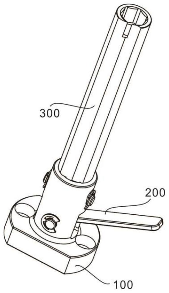
[0030] refer to Figure 1-6 , provides a schematic diagram of the overall structure of a torsion unloading mechanism, such as figure 1 , a torsional unloading mechanism includes a bearing unit 100 for carrying components, a base 101 for carrying components, a first circular sleeve 102 for accommodating and limiting the adjustment unit 200 , a seat for accommodating the adjustment unit 200 The inner space N1, the adjusting unit 200 for adjusting the mechanism, the roller 201 for rotating the adjusting unit 200, the first pin 202 for limiting the roller 201, the unloading unit 300 for unloading the torque, and the following roller 201 The upright column 301, which moves up and down, solves the problem that two or more bolt and nut combinations cannot be unloaded at the same time through the mutual cooperation between the adjustment unit and the unloading unit. The load-bearing unit provides stable working conditions for the mechanism. Ensure the normal use of the institution. ...
Embodiment 2
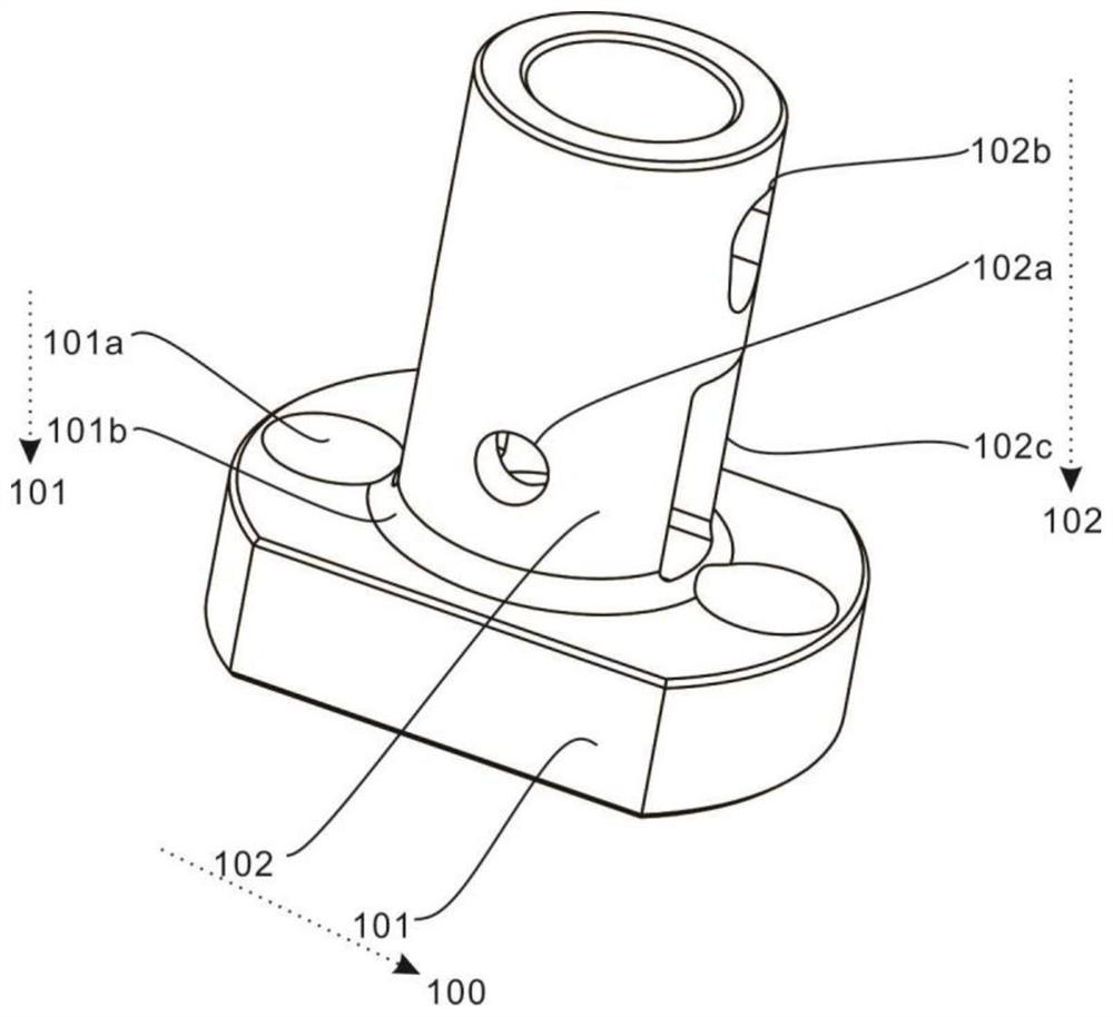
[0034] refer to figure 2 and 3 , this embodiment is different from the first embodiment in that: the bearing unit 100 for carrying the components also includes a limiting hole 101a that cooperates with screws to limit the base 101, and a hole 101a that fixes the first circular sleeve 102. The fixing ring 101b, the through hole 102a for limiting the adjustment unit 200, the inverted triangular groove 102b for limiting the unloading unit 300, the square groove 102c for allowing the adjustment unit 200 to rotate, and the position limiting for the unloading unit 300 The limit groove 102d, the first limit block 102e for limiting the roller 201, the limit hole 101a cooperates with the screw to fix the base 101, and the fixing ring 101b fixes the first circular sleeve 102, thereby ensuring the device normal use.
[0035]Specifically, the two sides of the base 101 that carries the components are provided with limiting holes 101a that cooperate with screws to limit the base 101, and...
Embodiment 3
[0039] refer to Figure 4 , this embodiment is different from the above embodiments in that: the adjustment unit 200 for adjusting the mechanism also includes a pressing rod 203 for driving the roller 201 to rotate and a first limit ring 202a for limiting the first pin 202, through Press the lever 203 to drive the roller 201 to rotate with the first pin 202 as the axis of rotation, so that the roller 201 is displaced upward while rotating with the first pin 202 as the axis of rotation, thereby driving the unloading unit 300 to move upward, The first limiting ring 202 a limits the first pin 202 , so as to ensure the normal operation of the adjustment unit 200 .
[0040] Specifically, the adjustment unit 200 for adjusting the mechanism also includes a pressure rod 203 that drives the roller 201 to rotate. The pressure rod 203 is fixedly connected to the outside of the roller 201. The pressure rod 203 passes through the square groove 102c and extends to the outside of the square ...
PUM
 Abstract
Description
Claims
Application Information
 - R&D Engineer
- R&D Manager
- IP Professional
- Industry Leading Data Capabilities
- Powerful AI technology
- Patent DNA Extraction
Browse by: Latest US Patents, China's latest patents, Technical Efficacy Thesaurus, Application Domain, Technology Topic, Popular Technical Reports.
© 2024 PatSnap. All rights reserved.Legal|Privacy policy|Modern Slavery Act Transparency Statement|Sitemap|About US| Contact US: help@patsnap.com