


Quick Research
Generate reliable direction feasibility study reports for your R&D in just a few steps.

Technical Q&A
Discover and master advanced knowledge NOW. Basics, ideas, possibilities, all at once.

Find Solutions
As an expert in R&D theories, this can generate solutions to your technical problems instantly.

Evaluate Feasibility
Analyze your overall solution with one click, know your potential R&D risks in advance.

Monitor Landscape
Get weekly tech updates, stay abreast of the latest tech innovations and key insights.
Positioning fitting type green plant fence mounting equipment
A technology for installing equipment and green plants, which is applied in the field of positioning and fitting green plant fence installation equipment, which can solve the problems of low manual installation efficiency and high installation position, and achieve a stable and beautiful layout
- Summary
- Abstract
- Description
- Claims
- Application Information
AI Technical Summary
Problems solved by technology
Method used
Image


Examples
Embodiment 1
[0035] A positioning and fitting type green plant enclosure installation equipment, such as Figure 1-7 As shown, it includes a positioning assembly 1, a lifting assembly 2 and a drilling nail assembly 3; there are two positioning assemblies 1, and the two positioning assemblies 1 are left and right symmetrical; a lifting assembly 2 is respectively arranged in front of the two positioning assemblies 1; A drilling nail assembly 3 is respectively connected to the lifting assembly 2 .
[0036] Wherein, the positioning assembly 1 on the right includes a first installation frame 101, a first electric slide rail 102, a first electric slider 103, an installation block 104 and a support frame 105; the inside front and inside of the first installation frame 101 A first electric slide rail 102 is respectively bolted to the rear; a first electric slider 103 is slidably connected between the two first electric slide rails 102; a mounting block 104 is fixedly connected to the upper side of...
Embodiment 2
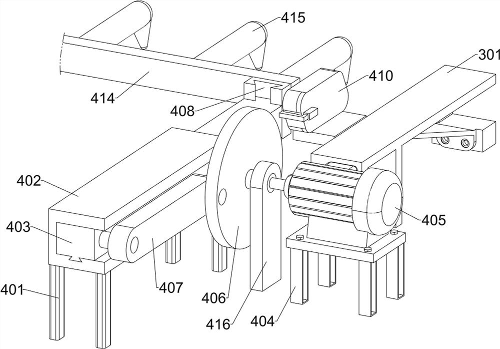
[0042] On the basis of Example 1, such as figure 1 and Figure 8-10 As shown, it also includes a bag opening assembly 4, the upper middle part of the two lifting assemblies 2 is connected with a bag opening assembly 4, and the left and right parts of the bag opening assembly 4 are connected with the drill assembly 3; the bag opening assembly 4 includes a transmission unit , the second connecting plate 414 and the curved hook 415; the upper middle parts of the two mounting plates 210 are respectively connected with a transmission unit, and the two transmission units are left and right symmetrical; the rear part between the two transmission mechanisms is connected with the second connecting plate 414; Several curved hooks 415 are welded on the rear side of the second connecting plate 414 , and every two curved hooks 415 form a group and are equidistantly arranged.
[0043] Wherein, the transmission unit on the right includes a first installation frame 401, a first limit slide r...
Embodiment 3
[0047] On the basis of Example 2, such as figure 1 , Figure 8 and Figure 11 As shown, a planting assembly 5 is also included, and the upper side of the two lifting assemblies 2 is connected with the planting assembly 5, and the planting assembly 5 is located inside the bag opening assembly 4; the planting assembly 5 includes a push unit, a half-ring push plate 510, a connecting rod 511 , the sixth mounting frame 512 and the guide rail 513; the upper sides of the two mounting plates 210 are respectively connected with a push unit; the two push units are left and right symmetrically arranged; the rear parts of the two push units are connected with a connecting rod 511; Several half-ring push plates 510 are welded equidistantly; a sixth mounting frame 512 is welded to the upper rear of the two mounting plates 210 , and several guide rails 513 are welded equidistantly to the rear of the sixth mounting frame 512 .
[0048] Wherein, the pushing unit on the right includes a third...
PUM
 Abstract
Description
Claims
Application Information
 - R&D Engineer
- R&D Manager
- IP Professional
- Industry Leading Data Capabilities
- Powerful AI technology
- Patent DNA Extraction
Browse by: Latest US Patents, China's latest patents, Technical Efficacy Thesaurus, Application Domain, Technology Topic, Popular Technical Reports.
© 2024 PatSnap. All rights reserved.Legal|Privacy policy|Modern Slavery Act Transparency Statement|Sitemap|About US| Contact US: help@patsnap.com