High-power single-resonant-cavity air-cooled laser light source suitable for laser deicing

A laser light source, high-power technology, applied in the direction of laser cooling device, structure/shape of optical resonator, laser, etc., can solve the difficulty of chemical deicing chemical agent spilling and smearing, the difficulty of chemical agent spilling and smearing, line The cable contact area is small and other problems, and the effect of high deicing efficiency, moderate output power density and low cost is achieved.

Inactive Publication Date: 2020-11-03
宝宇(武汉)激光技术有限公司
View PDF2 Cites 0 Cited by
  • Summary
  • Abstract
  • Description
  • Claims
  • Application Information

AI Technical Summary

Problems solved by technology

[0003] The common deicing methods mainly include: electric deicing, chemical deicing, mechanical deicing, etc. Among them, electric deicing and mechanical deicing require that the power transmission equipment must stop power supply; while chemical deicing has chemical agent splashing and It is difficult to smear, and the contact area for overhead cables is too small to remove the purpose of ice coating
In addition, many power transmission equipment are usually installed in places with poor road conditions such as steep mountain streams, hillsides, and cliffs, and power facilities such as high-voltage line towers are generally very high. Mechanical deicing is not only difficult but also slow. Chemical deicing Ice chemicals are very difficult to spill and smear

Method used


Image

  • High-power single-resonant-cavity air-cooled laser light source suitable for laser deicing
  • High-power single-resonant-cavity air-cooled laser light source suitable for laser deicing
  • High-power single-resonant-cavity air-cooled laser light source suitable for laser deicing

Examples


Embodiment Construction

[0028] In order to make the technical means, creative features, goals and effects achieved by the present invention easy to understand, the following will further explain how the present invention is implemented in conjunction with the accompanying drawings and specific implementation methods.

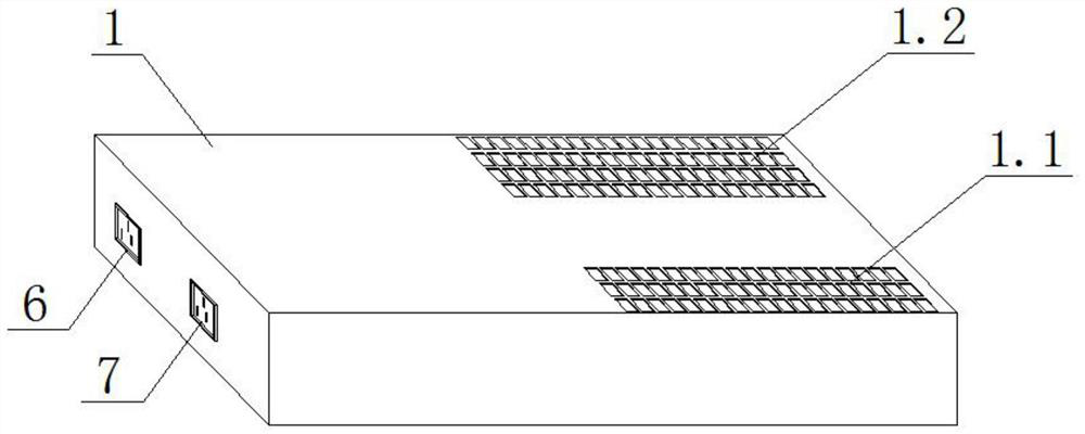
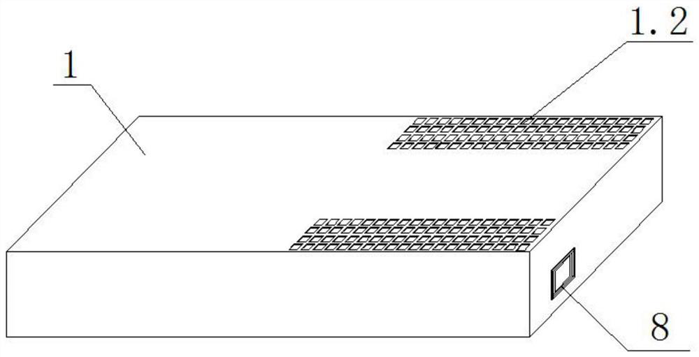
[0029] refer to figure 1 and figure 2 As shown, a high-power single-cavity air-cooled laser light source suitable for laser deicing provided by the present invention includes a light source housing 1, and a fixed substrate 2, an AC-DC conversion power supply 3, a DC The energy storage power supply 4 and the laser generating module 5 are provided with an AC-DC conversion power supply interface 6 , a DC energy storage power supply charging interface 7 and a laser light source control interface 8 outside the light source housing 1 .

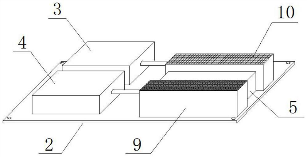
[0030] Specifically, as a specific embodiment of the present invention: see image 3 and Figure 4 As shown, the AC-DC conversion power supply 3, the DC...


PUM

PropertyMeasurementUnit
wavelengthaaaaaaaaaa
Gain coefficientaaaaaaaaaa

Abstract

The invention discloses a high-power single-resonant-cavity air-cooled laser light source suitable for laser deicing, and the light source comprises a light source housing which is internally providedwith a fixed substrate, an AC / DC conversion power supply, a DC energy storage power supply, and a laser generation module. An AC-DC conversion power supply interface, a DC energy storage power supplycharging interface and a laser light source control interface are arranged outside the light source shell; the AC-DC conversion power supply, the DC energy storage power supply and the laser generation module are arranged on the fixed substrate, the AC-DC conversion power supply is electrically connected with the AC-DC conversion power supply and the laser generation module, and the DC energy storage power supply is electrically connected with the DC energy storage power supply charging interface and the laser generation module. The laser generation module is electrically connected with the laser light source control interface. The light source has the advantages that the light source is convenient to use and does not need an external water cooler; the output power is high, light spots are large, and the deicing efficiency is high; the output power density is moderate, and a base material is not damaged; and a good body absorption effect can be formed to adapt to continuous work in acold environment.

Description

technical field [0001] The invention relates to a laser light source, in particular to a high-power single resonant cavity air-cooled laser light source suitable for laser deicing. Background technique [0002] In cold winter, when the temperature drops below 0°C, ice will form on high-voltage lines, substations, towers, high-altitude base stations, wind turbine blades and other power equipment in places with high humidity. When the wind speed is high, there will often be a lot of ice It is very serious to cause safety hazards to the operation of power equipment and reduce power transmission / generation efficiency. In my country, power generation / transmission is mainly in the northwestern region, where the winter is cold and long and the freezing situation is serious; although the freezing time in the southeastern coastal area is short in winter, its humidity is often relatively high and it is easy to form ice on the power facilities. Therefore, it is particularly important ...

Claims


Application Information

Patent Timeline
Patent Type & Authority Applications(China)
IPC IPC(8): H01S3/04H01S3/08H01S3/091H01S3/10H01S3/11
CPCH01S3/0404H01S3/08H01S3/0912H01S3/10007H01S3/11
Inventor 李震湛欢刘梅丁铮陈建王亦军汤磊辛志文陈文忠
Owner 宝宇(武汉)激光技术有限公司
Why Eureka
Try Eureka