Pin header feeding and assembling device and method for pin header female connector production

A technology of a female connector and an assembling device, which is applied in the field of needle-arranging feeding and assembling devices, can solve the problems of conveying efficiency and poor conveying positioning of the needle-arranging material belt, so as to improve the accuracy of conveying and positioning, and improve the cutting efficiency and cutting quality. Effect

Inactive Publication Date: 2020-11-03
陈如会
View PDF0 Cites 0 Cited by
  • Summary
  • Abstract
  • Description
  • Claims
  • Application Information

AI Technical Summary

Problems solved by technology

[0005] The purpose of the present invention is to solve the above-mentioned problems of poor conveying efficiency and conveying positioning of the existing pin strips, and provide a pin strip feed assembly device for the production of pin strip female connectors. The assembly and the needle conveying assembly cooperate with each other to facilitate the orderly conveying and feeding of the needle strip; through the cooperation of the needle conveying limit plate and the needle conveying cover, it is convenient to limit the needle strip and improve the conveying stability , through the cooperation of the needle row conveying drive tooth plate and the needle strip material belt to improve the positioning accuracy of the conveying; through the needle row cutting and inserting components to improve the quality of the needle cutting and insertion; through the needle waste bending components to facilitate the subsequent removal of the needle waste with cropping

Method used


Image

  • Pin header feeding and assembling device and method for pin header female connector production
  • Pin header feeding and assembling device and method for pin header female connector production
  • Pin header feeding and assembling device and method for pin header female connector production

Examples


Embodiment Construction

[0029] The specific implementation manner of the present invention will be described in detail below in conjunction with the accompanying drawings.

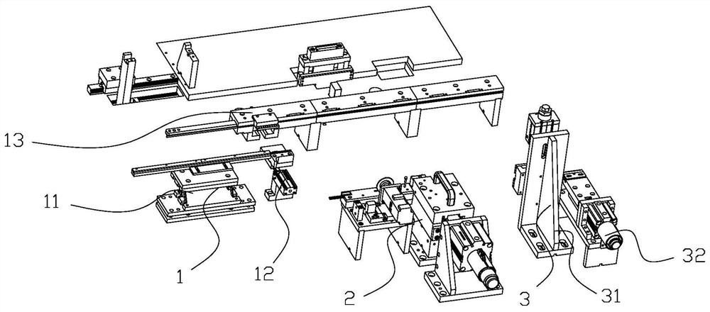
[0030] Such as figure 1 As shown, a pin header connection terminal production equipment, the equipment includes a frame and its upper row of female feeding and conveying device 1, pin header feeding assembly device 2 and pin header cutting and pressing device 3; The device 1 is used to convey and feed the female header and carry out horizontal conveyance; the needle header feeding assembly device 2 is located on the front side of the female header feeding conveying device 1, and the needle header feeding assembly device 2 is used to feed the needle header strip. And insert the needle row into the female header; the needle row cutting and pressing device 3 is located on the discharge end side of the needle row feeding assembly device 2, and the needle row cutting and pressing device 3 is used to cut the needle strip and Press the...


PUM


Abstract

The invention belongs to the technical field of automatic production of electronic connectors. The invention discloses a pin header feeding and assembling device for pin header connecting terminal production. The pin header feeding and assembling device comprises a pin header feeding assembly, a pin header conveying assembly, a pin header cutting and inserting assembly and a pin header waste bending assembly. The pin header feeding assembly conveys a pin header material belt to the pin header conveying assembly. The pin header conveying assembly is used for conveying a pin header material beltto the pin header cutting assembly in order, and the pin header cutting and inserting assembly is connected with the discharging end of the pin header conveying assembly. The pin header cutting and inserting assembly is used for cutting a group of pin header strips and then clamping and inserting the pin header strips into the female header; the pin header waste bending assembly is used for bending pin header waste on the pin header material belt. The pin header conveying device has the advantages that the pin header conveying efficiency and conveying positioning accuracy are improved, the pin header cutting efficiency and cutting quality are improved, and the quality is improved through pin header insertion.

Description

technical field [0001] The invention belongs to the technical field of automatic production of electronic connectors, and in particular relates to a pin row feed assembly device and method for producing pin row female connectors. Background technique [0002] The pin header connection terminal is a kind of electrical connector, which is widely used in the pcb circuit boards of electronics, electrical appliances, and instruments. The function of the bridge is to undertake the task of electric current or signal transmission. [0003] The pin row connection terminal includes a female row and a pin row, and a plurality of regularly arranged pin row slots are arranged horizontally on the upper part of the female row, and a plurality of regularly arranged pin row slots are inserted into the pin row slots. During the production of the existing pin header connecting terminal, the female header and the pin header strip are firstly fed. The pin strip is composed of a long strip of wa...

Claims


Application Information

Patent Timeline
IPC IPC(8): H01R43/20B21F11/00B21F15/00B21F23/00
CPCB21F11/00B21F15/00B21F23/00H01R43/20
Inventor 陈如会张新芹
Owner 陈如会
Why Eureka
Try Eureka