
Streamline tunnel type rotating fluid machine runner design and forming method

A fluid machinery, tunnel-type technology, applied in mechanical equipment, liquid fuel engines, non-variable-capacity engines, etc., can solve the problems of lack of depth, no mention of flow channel forming, and less research on streamlined tunnel-type rotating machinery. Achieve the effect of smooth transition of curvature, smooth curvature change, and small flow loss

Pending Publication Date: 2020-11-03
科诺泰博(北京)科技有限公司
View PDF5 Cites 4 Cited by
  • Summary
  • Abstract
  • Description
  • Claims
  • Application Information

AI Technical Summary

Problems solved by technology

U.S. Patents US4029431, US4278397 and US4293278 disclose the structure of the axial flow streamline tunnel type rotary fluid machine, and international patents WO2004 / 022921A1 and WO2011 / 042863A2 disclose the structure of the radial flow streamline tunnel type rotary fluid machine, but neither mentions About the content of runner forming;
[0004] At present, there are few and in-depth studies on streamlined tunnel-type rotating machinery, especially the lack of research on its design and forming methods

Method used


Image

  • Streamline tunnel type rotating fluid machine runner design and forming method
  • Streamline tunnel type rotating fluid machine runner design and forming method
  • Streamline tunnel type rotating fluid machine runner design and forming method

Examples


Embodiment

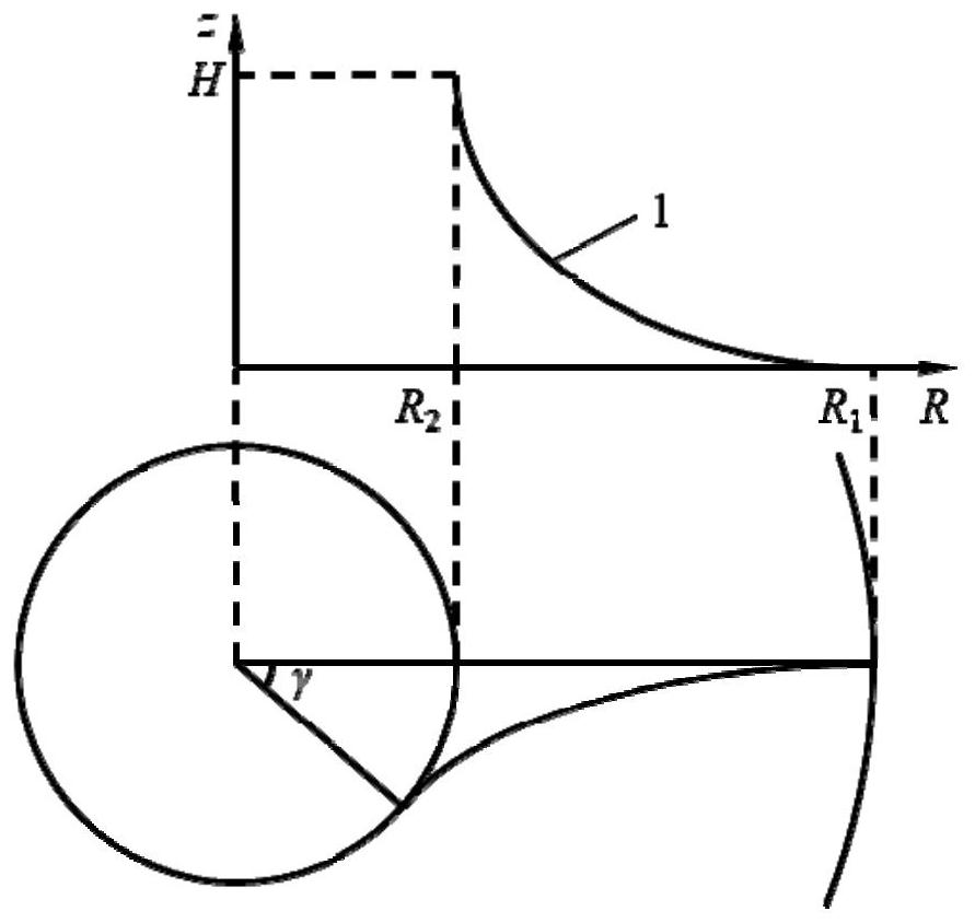
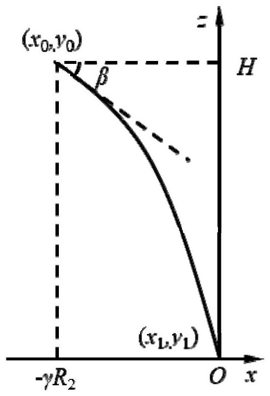
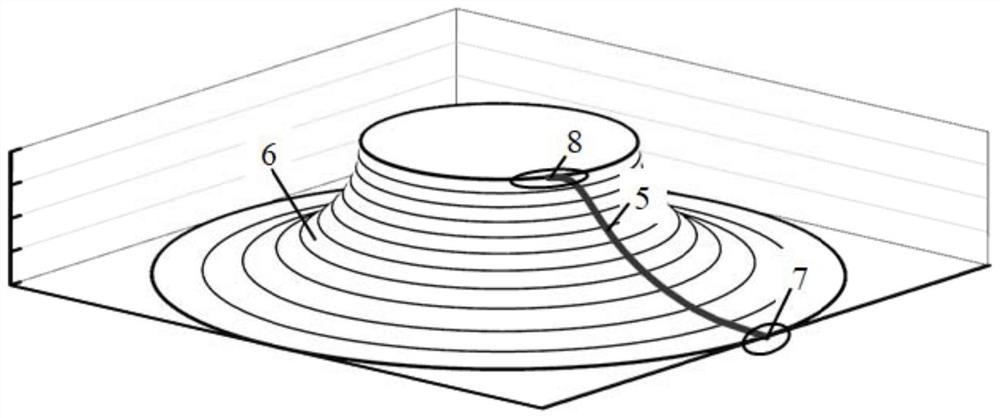
[0031] Such as Figure 1-Figure 5 As shown, the present invention provides a flow channel design and forming method of a streamline tunnel type rotary fluid machine, and the design and forming method includes the following steps:

[0032] S1: Constraint parameters obtained from one-dimensional design include: the radius of the two ends of the centerline far end point 7 and the centerline near end point 8 of the flow channel, and the structure at the two ends of the centerline far end point 7 and the centerline near end point 8 Angle, and assuming the envelope angle of the flow channel, the axial (z-axis direction) distance between the far end point 7 of the center line and the near end point 8 of the center line;

[0033] S2: Considering the near-central point 8 on the center line of the runner, which is closer to the axis, for a single-stage centripetal turbine or centrifugal compressor, the absolute velocity at the near-end point 8 of the centerline is generally close to the...


PUM


Abstract

The invention discloses a streamline tunnel type rotating fluid machine runner design and forming method. The method comprises the following steps: S1, obtaining relevant constraint parameters obtained through one-dimensional design; s2, obtaining a central line expansion projection curve and constructing the central line expansion projection curve into a cubic Hermite curve; s3, after a central line expansion projection curve is obtained, restoring an expansion plane into a cylindrical surface to obtain an equation of the cylindrical surface projection curve; s4, if the meridian form is known, easily obtaining an annular curved surface equation where the center line is located; s5, combining the cylindrical projection curve and the annular curved surface equation to obtain an equation ofan actual runner center line; s6, obtaining the inlet and outlet areas of the runner according to the flow characteristics and speed conditions of the rotary machine, thereby forming a complete runner. The method is easy to expand to streamline design of more fluid machines through a combined equation method, is suitable for media such as gas, liquid, solid powder and multi-phase mixed fluid, forms a design system from streamlines to runners and from low dimension to high dimension, and can make more reasonable prediction on mechanical properties.

Description

technical field [0001] The invention relates to the field of rotary fluid machinery, in particular to a flow channel design and forming method of streamline tunnel type rotary fluid machinery. Background technique [0002] Rotation is the most common movement in the world, and rotary machinery is the most widely used machinery in the world, while rotary impeller machinery, such as gas turbines, steam turbines, turbochargers, fans, fans, rotary compressors, rotor pumps, etc., are the most widely used in today's society. Important fluid machinery and power transmission. Its medium involves various media forms such as gas, liquid, solid powder, and even multi-phase mixed fluid. For any kind of machinery and medium, whether the internal streamline can complete the required turning and whether the streamline is smooth and smooth are the decisive factors for the mechanical and mechanical properties. [0003] Today's mainstream vane impeller machinery theory research is mature an...

Claims


Application Information

Patent Timeline
Patent Type & Authority Applications(China)
IPC IPC(8): G06F30/17G06F30/28F01D1/34F04D29/18F04D29/26
CPCG06F30/17G06F30/28F01D1/34F04D29/18F04D29/26
Inventor 黄若郭文杰
Owner 科诺泰博(北京)科技有限公司
Learn More