Concrete pouring device and method for shield launching base

A concrete and foundation technology, which is applied in the direction of earth drilling, mining equipment, tunnels, etc., can solve the problems affecting the pouring quality of the starting foundation of shield tunneling, the difficulty of keeping the concrete in a fixed position, and the restriction of the layout of detection points, etc., to ensure the pouring Quality, installation is simple and convenient, and the effect of controlling construction accuracy

Active Publication Date: 2020-11-03
CCCC TUNNEL ENG
View PDF13 Cites 0 Cited by
  • Summary
  • Abstract
  • Description
  • Claims
  • Application Information

AI Technical Summary

Problems solved by technology

[0004] 1. To precisely control the pouring of the arc surface, it is necessary to arrange a large number of detection points and install detection modules, and the workload is relatively large;
[0005] 2. Concrete pouring is a dynamic process, which severely limits the layout of detection points and greatly affects the quality of measurement
[0006] 3. The poured concrete has a certain fluidity. After pouring concrete on the arc surface, it is difficult to maintain a fixed position for the poured concrete, which affects the pouring quality of the shield starting base;
[0007] 4. Manual control of pouring is more dependent on the experience of construction personnel

Method used


Image

  • Concrete pouring device and method for shield launching base
  • Concrete pouring device and method for shield launching base
  • Concrete pouring device and method for shield launching base

Examples


Embodiment Construction

[0037] The technical solution of the present invention will be further described below in conjunction with the accompanying drawings.

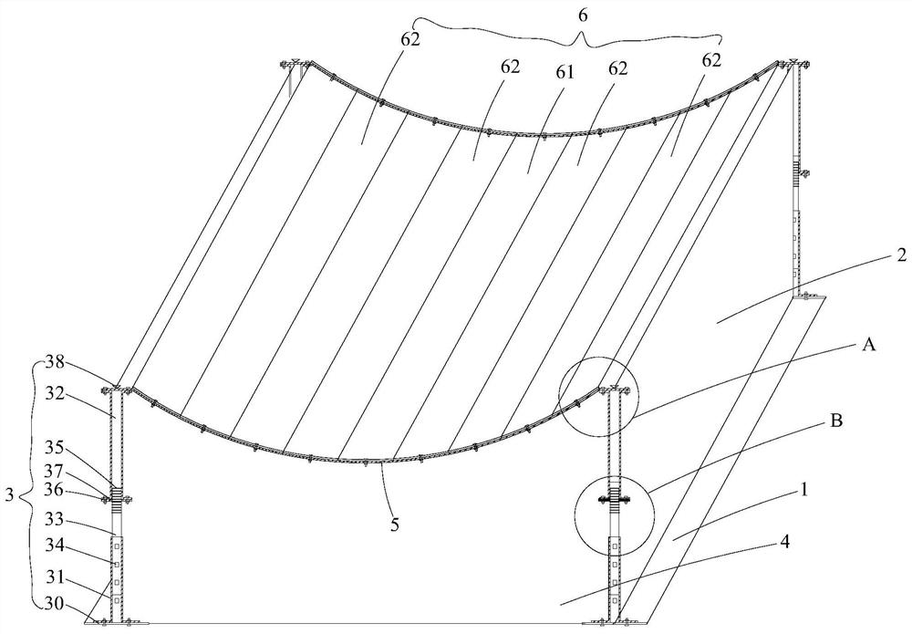
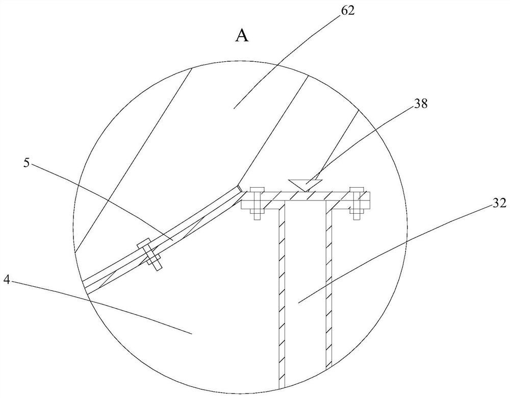
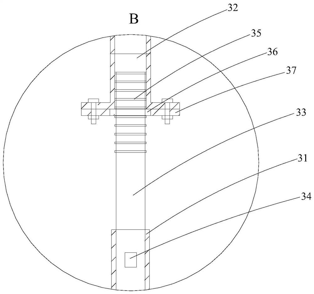
[0038] The invention relates to the improvement of the concrete pouring of the starting base of the shield machine, so as to solve many problems existing in the arc surface pouring of the current starting base of the shield machine. The present invention innovatively proposes a concrete pouring device for the starting base of the shield machine. The formwork body, arc-shaped top beam and multiple top plates arranged on the basis of the side plates can form a circular-arc surface at the top for pouring. When pouring, it is only necessary to install the formwork body and the arc-shaped top beam, and then pour concrete while installing the top plate, which can effectively ensure the quality of concrete pouring on the arc surface.

[0039] see Figure 1-3 As shown, a concrete pouring device for the starting base of the shield machine is shown, wh...


PUM


Abstract

The invention discloses a pouring device and a pouring method. The pouring device comprises a bottom plate, two sets of formwork assemblies and two first side plates installed between the two sets offormwork assemblies. Each formwork assembly comprises two formwork bodies, a second side plate installed on the portion, between the two formwork bodies, of the bottom plate, and an arc-shaped top beam with the two ends connected to the tops of the two formwork bodies correspondingly and bent downwards in an arc shape, the pouring device further comprises a plurality of top plates with the two ends correspondingly connected to the two arc-shaped top beams in the two sets of formwork assemblies correspondingly. The bottom plate, the two sets of formwork assemblies, the two first side plates andthe multiple top plates can define a concrete pouring space in a matched manner. According to the pouring device, the formwork bodies, the arc-shaped top beams and the multiple top plates which are arranged on the basis of the side plates can define the pouring space with the top forming the arc surface, during pouring, only the formwork bodies and the arc-shaped top beams need to be installed, then concrete is poured while the top plates are installed, and the concrete pouring quality of the arc surface can be effectively guaranteed.

Description

technical field [0001] The invention relates to the field of pouring of a shield starting base, in particular to a concrete pouring device and a pouring method for a shield starting base. Background technique [0002] The main function of the shield starting base is to place the shield machine safely and accurately, bear the gravity of the shield machine itself and the friction force during propulsion, and ensure that the shield machine can be safely assembled, debugged and launched. The design of the starting base of the shield must have sufficient strength, rigidity and installation accuracy. When pouring the starting base of the shield machine, it is necessary to strictly control the pouring elevation, slope, radian, etc. The construction quality of the starting base of the shield machine will directly affect the installation stress, starting attitude and thrust of the shield machine. [0003] At present, for the pouring of the arc surface on the top of the starting base...

Claims


Application Information

Patent Timeline
Patent Type & Authority Applications(China)
IPC IPC(8): E21D9/06E21D9/00
CPCE21D9/06E21D9/00
Inventor 赵小鹏宋帮红闵凡路张政恺
Owner CCCC TUNNEL ENG
Why Eureka
Try Eureka