


Quick Research
Generate reliable direction feasibility study reports for your R&D in just a few steps.

Technical Q&A
Discover and master advanced knowledge NOW. Basics, ideas, possibilities, all at once.

Find Solutions
As an expert in R&D theories, this can generate solutions to your technical problems instantly.

Evaluate Feasibility
Analyze your overall solution with one click, know your potential R&D risks in advance.

Monitor Landscape
Get weekly tech updates, stay abreast of the latest tech innovations and key insights.
A hole opener for aluminum foil capping vials for injection medicine in respiratory department
A technology for injection and hole opener, which is applied in the directions of bottle/container cap, opening closed container, application, etc., can solve the problem of inconvenient insertion of the bottle needle into the medicine bottle, etc., and achieve the effect of convenient hole opening
- Summary
- Abstract
- Description
- Claims
- Application Information
AI Technical Summary
Problems solved by technology
Method used
Image

Examples
Embodiment 1
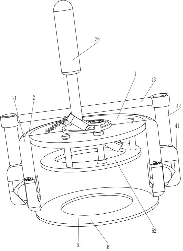
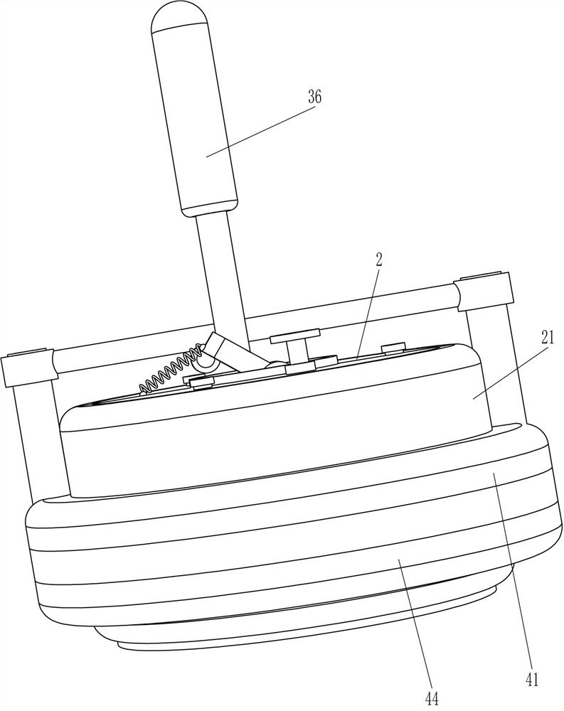
[0025] A kind of opener for the aluminum foil cap opening of medicine bottle for respiratory department injection, such as Figure 1-5 As shown, it includes a mounting plate 1, a fixing mechanism 2 and an opening mechanism 3, and the fixing mechanism 2 and the opening mechanism 3 are installed on the mounting plate 1 respectively.
[0026] The fixing mechanism 2 includes a fixing tube 21 , and the fixing tube 21 is connected to the outer wall of the mounting plate 1 .
[0027] The opening mechanism 3 includes a mounting ring 31, a rotating shaft 32, a hinged rod 33, a ring knife 34, a first spring 35, and a handle 36. The middle part of the mounting plate 1 is embedded with a mounting ring 31, and the inner wall of the mounting ring 31 is rotatably connected to a rotating shaft 32. The rotating shaft 32 is connected with a hinged rod 33, the top of the hinged rod 33 is connected with a handle 36, the right side of the hinged rod 33 is connected with a ring knife 34, and the fi...
Embodiment 2
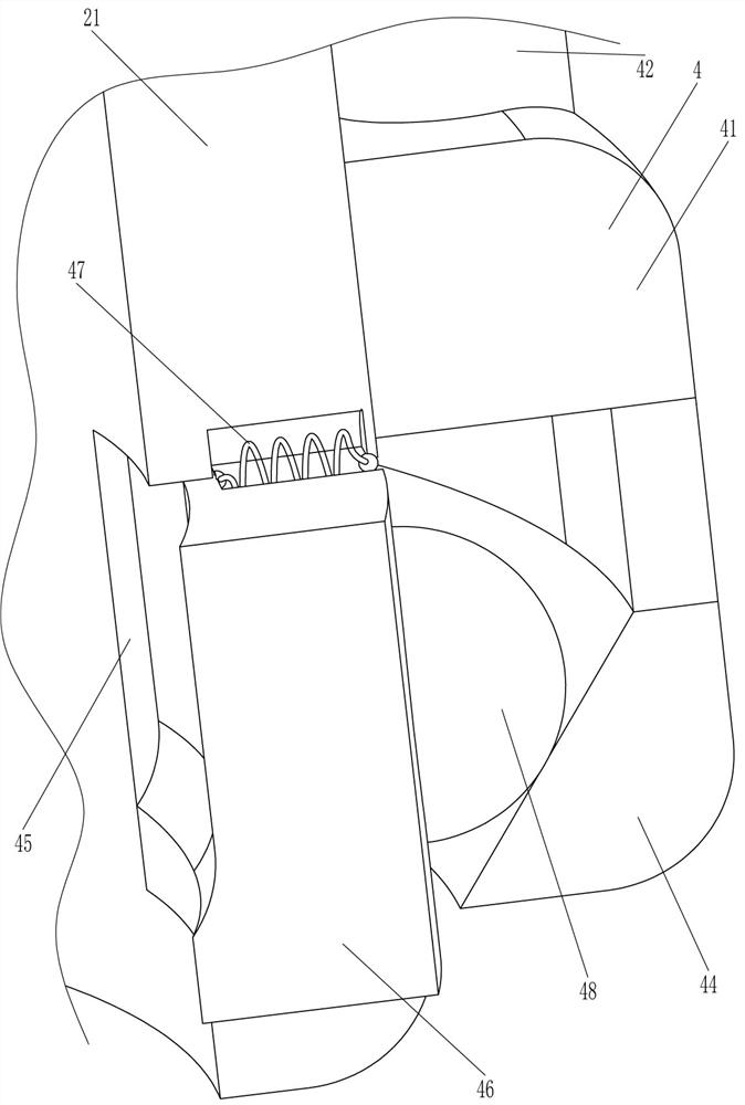
[0030] On the basis of Example 1, such as Figure 1-4 As shown, a locking mechanism 4 is also included, and the locking mechanism 4 includes a sliding tube 41, a connecting rod 42, a contact rod 43, a taper sleeve 44, a pressing block 46, a second spring 47, a protrusion 48 and a rolling shaft 49, fixed The outer wall of the tube 21 is slidably connected with a sliding tube 41, the left and right sides of the top of the sliding tube 41 are connected with connecting rods 42, and a contact rod 43 is connected between the tops of the two connecting rods 42, and the contact rod 43 is located at the rear side of the handle 36 , the bottom of the sliding tube 41 is connected with a taper sleeve 44, the inner wall of the taper sleeve 44 is slidingly connected with the outer wall of the fixed tube 21, the left and right sides of the lower part of the fixed tube 21 are provided with chute 45, and the chute 45 is slidingly connected with a pressure Block 46, the second spring 47 is conn...
Embodiment 3
[0033] On the basis of Example 2, such as Figure 5 As shown, an adjustment mechanism 5 is also included, and the adjustment mechanism 5 includes a guide rod 51, a limit plate 52, a screw rod 53, a nut 54 and a shaft sleeve 55, and there are multiple sliding connections evenly spaced along the circumferential direction on the mounting plate 1. Guide rod 51, the limit plate 52 is connected between the bottom ends of multiple guide rods 51, the nut 54 is fixedly connected to the top of the mounting plate 1, the nut 54 is connected with the screw rod 53 by threaded connection, the limit plate 52 top is provided with Axle sleeve 55, screw rod 53 bottom is threadedly connected with axle sleeve 55.
[0034] The screw rod 53 can be turned clockwise or counterclockwise, so that the screw rod 53 can move up or down, so that the limit plate 52 can be moved up or down, and when the limit plate 52 moves to a suitable position, the rotation stops Screw 53. The limit plate 52 can limit th...
PUM
 Abstract
Description
Claims
Application Information
 - R&D Engineer
- R&D Manager
- IP Professional
- Industry Leading Data Capabilities
- Powerful AI technology
- Patent DNA Extraction
Browse by: Latest US Patents, China's latest patents, Technical Efficacy Thesaurus, Application Domain, Technology Topic, Popular Technical Reports.
© 2024 PatSnap. All rights reserved.Legal|Privacy policy|Modern Slavery Act Transparency Statement|Sitemap|About US| Contact US: help@patsnap.com