Plantain core slicing device
A slicing device and plantain core technology, which is applied in metal processing and other directions, can solve the problem that fingers are easily cut by kitchen knives, and achieve the effect of protecting fingers and preventing cuts
- Summary
- Abstract
- Description
- Claims
- Application Information
AI Technical Summary
Problems solved by technology
Method used
Image
Examples
Embodiment 1
[0023] A banana core slicing device, such as Figure 1-5 As shown, it includes a bottom plate 1, a support column 2, a fixed plate 3, a collection box 4, a cutting device 5 and a feeding device 6. The top of the bottom plate 1 is connected with two supporting columns 2, and the two supporting columns 2 are symmetrical on both sides. A fixing plate 3 is connected between the tops of the supporting columns 2 , a collecting box 4 is connected to the right side of the top of the bottom plate 1 , a cutting device 5 is installed on the right side of the fixing plate 3 , and a feeding device 6 is installed on the top of the fixing plate 3 .
[0024] The cutting device 5 includes a first bearing seat 51 , a first rotating shaft 52 , a rotary cutter 53 , a mounting shell 54 and a rocker 55 . A first bearing seat 51 is connected to the top, a first rotating shaft 52 is connected to the first bearing seat 51, the right end of the first rotating shaft 52 passes through the installation sh...
Embodiment 2
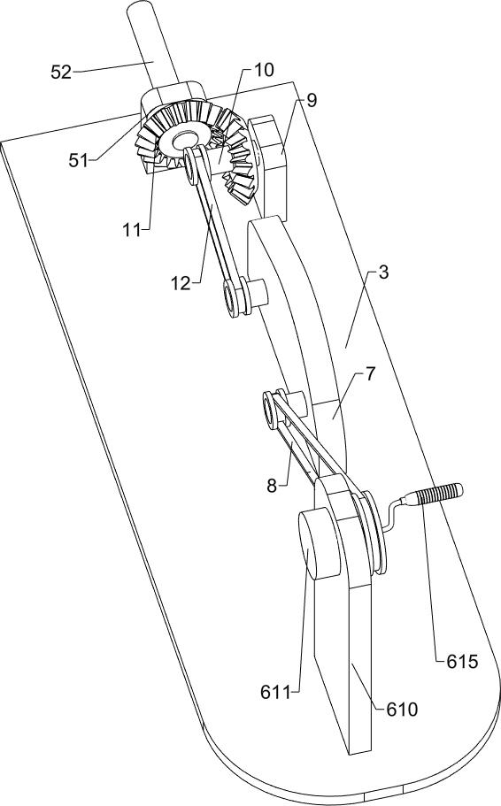
[0028] On the basis of Example 1, as Figure 5 As shown, it also includes a reduction box 7, a first belt transmission mechanism 8, a fourth bearing seat 9, a fourth rotating shaft 10, a bevel gear 11 and a second belt transmission mechanism 12, and a fixed plate 3 on the right side of the third bearing seat 610. A reduction box 7 is installed on the top, a first belt transmission mechanism 8 is connected between the output end of the reduction box 7 and the third rotating shaft 611, and a fourth bearing seat 9 is connected to the top of the fixed plate 3 on the right side of the reduction box 7, and the fourth bearing The seat 9 is connected with a fourth rotating shaft 10 , the fourth rotating shaft 10 and the left end of the first rotating shaft 52 are connected with bevel gears 11 , the two bevel gears 11 are meshed, and the rear end of the fourth rotating shaft 10 is connected with the input end of the reduction box 7 . A second belt conveying mechanism 12 is connected th...
Embodiment 3
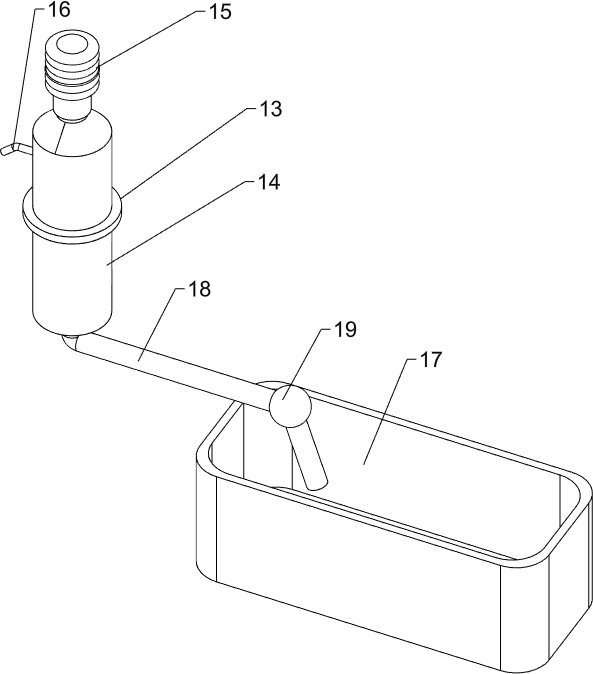
[0031] On the basis of Example 2, as Image 6As shown, it also includes a cylindrical sleeve 13, a water storage cylinder 14, a water press 15, a water outlet pipe 16, a water tank 17, a water suction pipe 18 and a one-way valve 19. The left side of the installation shell 54 is provided with a circular hole 20. A cylindrical sleeve 13 is connected to the fixed plate 3 on the front side of the bearing seat 51, the cylindrical sleeve 13 is connected with a water storage cylinder 14, the water storage cylinder 14 penetrates the fixed plate 3, and the top of the water storage cylinder 14 is provided with a water press 15. The right side of 14 is connected with a water outlet pipe 16, the water outlet pipe 16 is located in the circular hole 20, the bottom of the water storage cylinder 14 is connected with a water suction pipe 18, and the water suction pipe 18 and the water outlet pipe 16 are connected with a one-way valve 19, the top front side of the bottom plate 1 A water tank 17...
PUM
 Abstract
Description
Claims
Application Information
 - Generate Ideas
- Intellectual Property
- Life Sciences
- Materials
- Tech Scout
- Unparalleled Data Quality
- Higher Quality Content
- 60% Fewer Hallucinations
Browse by: Latest US Patents, China's latest patents, Technical Efficacy Thesaurus, Application Domain, Technology Topic, Popular Technical Reports.
© 2025 PatSnap. All rights reserved.Legal|Privacy policy|Modern Slavery Act Transparency Statement|Sitemap|About US| Contact US: help@patsnap.com


