Manipulator device with stable clamping function

A manipulator and stable technology, applied in the field of manipulators, can solve the problems of affecting the production efficiency of workpieces, large clamping force, and small clamping force, and achieve the effect of convenient clamping, reasonable structure and protection of workpieces

Inactive Publication Date: 2020-11-03
熊祥
View PDF0 Cites 4 Cited by
  • Summary
  • Abstract
  • Description
  • Claims
  • Application Information

AI Technical Summary

Problems solved by technology

In order to improve the efficiency of industrial production and processing, manipulators are often used to grip and move objects. The existing manipulators tend to have too much gripping force when gripping workpieces, causing damage to the workpieces; During the process of the workpiece, the workpiece will fall off, which will affect the production efficiency of the workpiece

Method used


Image

  • Manipulator device with stable clamping function
  • Manipulator device with stable clamping function
  • Manipulator device with stable clamping function

Examples


Embodiment 1

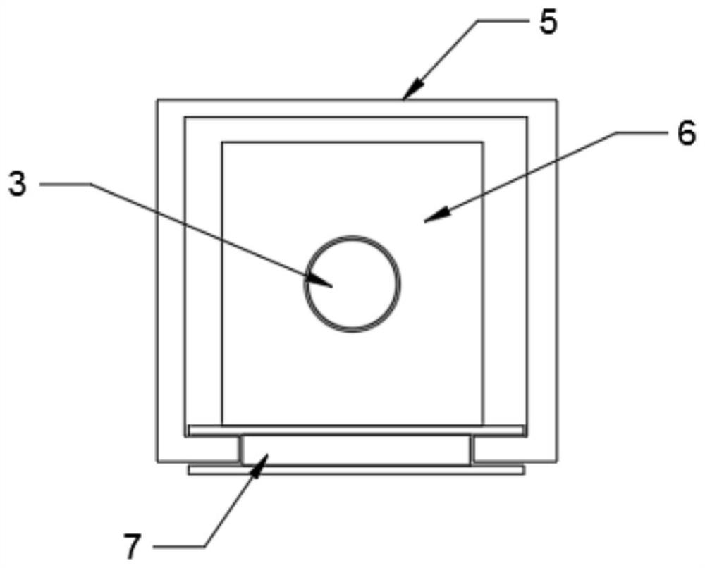
[0023] see Figure 1~4 , in the embodiment of the present invention, a manipulator device with stable clamping includes a motor frame 1, a fixed frame 5 and a fixed frame 10, a first motor 2 is installed inside the motor frame 1, and a first motor 2 is installed at the front end of the shaft of the first motor The first threaded rod 3, the first rolling bearing 4 is installed on the front end of the first threaded rod 3, the slider 6 is installed on the outside of the first threaded rod 3, the fixed frame 5 is installed on the front side of the motor frame 1, and the middle part of the slider 6 is provided with a screw hole , the inner side of the screw hole is meshed with the outer side of the first threaded rod 3, and the first rolling bearing 4 is installed at the connection between the first threaded rod 3 and the fixed frame 5; The shape is I-shaped; telescopic motor 8 is installed at the bottom of limit plate 7, fixed plate 9 is installed at the front end of telescopic m...

Embodiment 2

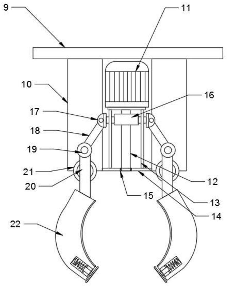
[0026] see Figure 5 , in the embodiment of the present invention, a manipulator device with stable clamping includes a motor frame 1, a fixed frame 5 and a fixed frame 10, a first motor 2 is installed inside the motor frame 1, and a first motor 2 is installed at the front end of the shaft of the first motor The first threaded rod 3, the first rolling bearing 4 is installed on the front end of the first threaded rod 3, the slider 6 is installed on the outside of the first threaded rod 4, the fixed frame 5 is installed on the front side of the motor frame 1; the bottom end of the slider 6 is installed with a limit Plate 7, telescopic motor 8 is installed on the bottom end of the limit plate 7, fixed plate 9 is installed on the front end of the telescopic motor 8, fixed frame 10 is installed on the left and right sides of the bottom end of the fixed plate 9, and the second motor is installed on the middle part of the bottom end of the fixed plate 9 11. The cross-sectional shape ...


PUM


Abstract

The invention discloses a manipulator device with a stable clamping function. The device comprises a motor frame, a fixing frame and a fixing bracket, a first motor and a first threaded rod are installed at the inner side of the motor frame, and a sliding block and the fixing frame are arranged at the outer side of the first threaded rod; a limiting plate is installed at the bottom end of the sliding block, a telescopic motor and a fixing plate are installed at the bottom end of the limiting plate, a second motor and a second threaded rod are installed in the middle of the bottom end of the fixing plate, and limiting rods are arranged at the left and right sides of the second threaded rod; a cylinder is installed at the outer side of the second threaded rod, a first rotating shaft, a firstconnecting rod, a second rotating shaft, a second connecting rod and a third rotating shaft are installed at the outer side of the cylinder, and a clamping plate is installed at the bottom end of thesecond connecting rod; and a groove is formed in the bottom end of the clamping plate, a pressure sensor is installed at the bottom end of the inner side of the groove, a short rod is installed at the front end of the pressure sensor, a limiting ring and a spring are installed at the outer side of the short rod, and a pressing plate is installed at the front end of the short rod. The manipulatordevice is reasonable in structure, a manipulator can conveniently clamp a workpiece, the workpiece is effectively protected, and the working efficiency is improved.

Description

technical field [0001] The invention relates to the technical field of manipulators, in particular to a gripping and stable manipulator device. Background technique [0002] Automated production technology can effectively shorten and stabilize the production cycle, which not only improves production efficiency, but also reduces production costs. Therefore, manipulators using automated production technology have been widely used in production in recent years. The robotic arm is currently the most widely used automated mechanical device in the field of robotics. It can be seen in industrial manufacturing, medical treatment, entertainment services, military, semiconductor manufacturing, and space exploration. Although their The shapes are different, but they all have a common feature, that is, they can accept instructions and accurately locate a certain point in three-dimensional (or two-dimensional) space for operation; in industry, manipulators can replace human heavy labor t...

Claims


Application Information

Patent Timeline
Patent Type & Authority Applications(China)
IPC IPC(8): B25J9/02B25J13/08B25J15/02
CPCB25J9/023B25J13/085B25J15/022
Inventor 熊祥
Owner 熊祥
Why Eureka
Try Eureka