A self-locking clamping device for automatic machining

A mechanical processing and self-locking clip technology, applied in the field of mechanical processing, can solve the problems of affecting processing, increasing the number of defective products, increasing the impact force and friction force, etc., to achieve the effect of convenient transportation, convenient reprocessing and good effect.

Active Publication Date: 2022-06-17
临沂联发机械有限公司
View PDF6 Cites 0 Cited by
  • Summary
  • Abstract
  • Description
  • Claims
  • Application Information

AI Technical Summary

Problems solved by technology

[0007] In order to solve the above-mentioned technical problems, the present invention provides a self-locking clamping device for automatic machining to solve the problem of increased impact force and friction when the nut is processed. The existing clamping device simply clamps the nut The side of the nut is clamped, the nut may be clamped in an inclined state, and the iron filings formed during the nut processing will adhere to the processing platform, and the iron filings need to be removed in time. When the iron filings are not cleaned, the nut will also It is in a tilted state, which affects the processing and increases the number of defective nuts after processing; the nuts need to be taken out manually after the nuts are processed, and the nuts are also manually placed on the clamping device when the nuts are placed, requiring multiple processes It is troublesome and a waste of time to complete

Method used


Image

  • A self-locking clamping device for automatic machining
  • A self-locking clamping device for automatic machining
  • A self-locking clamping device for automatic machining

Examples


Embodiment

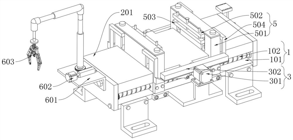
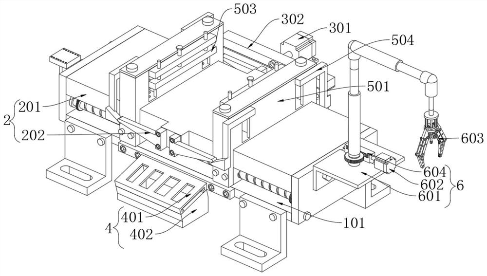
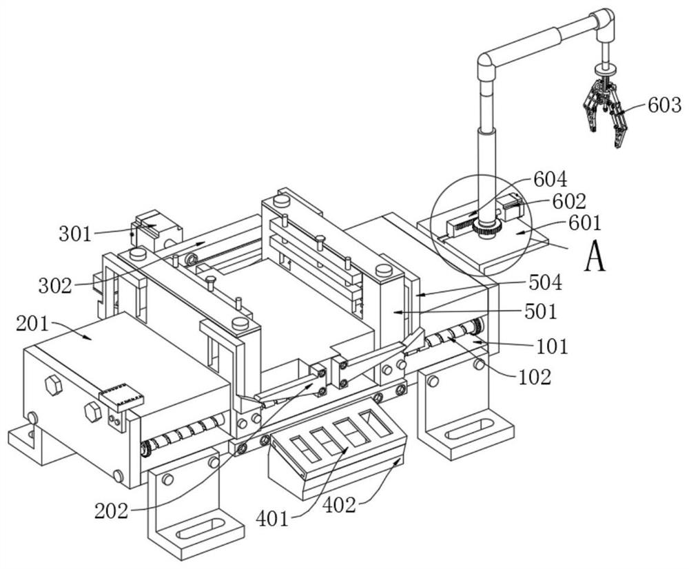
[0041] as attached figure 1 to the attached Figure 13 shown:

[0042] The invention provides a self-locking clamping device for automatic machining, comprising a fixing mechanism 1; the fixing mechanism 1 is provided with two sets of L-shaped fixing plates, and the fixing plates are provided with through holes for convenient connection with the body; The mechanism 1 includes a base 101, a threaded rod 102 and a servo motor 103. Two threaded rods 102 that are rotationally connected are symmetrically installed on the connecting plate of the rectangular base 101, and a gear is installed on the threaded rod 102; the middle position of the base 101 is installed There is a servo motor 103 with a gear, and the gear on the servo motor 103 meshes with the gear on the threaded rod 102, and the other ends of the two threaded rods 102 are connected by a chain, then when the servo motor 103 rotates, the two The two threaded rods 102 can rotate in the same direction, so that the threaded...


PUM


Abstract

The invention provides a self-locking clamping device for automatic mechanical processing, which includes a fixing mechanism; two sets of L-shaped fixing plates are installed on the fixing mechanism, and a through hole is opened on the fixing plate to facilitate the connection with the machine body; Two rectangular connecting plates are symmetrically installed on the fixing mechanism through bolts, and a rotating connecting seat connected with the connecting mechanism is installed on the fixing mechanism, and the two groups of connecting seats are opposite to each other; the fixing mechanism is fixed with bolts a connecting mechanism. A cylinder A fixedly connected is set on the processing platform, a rectangular push rod is set on the cylinder A, a rubber block is set on the bottom of the push rod, and a snap-fit ​​collection box is set on the processing platform, when the cylinder A works, it will Push the push rod to slide on the processing platform, thereby pushing the processed nuts to the outside, and the rubber block will scrape the iron chips into the collection mechanism for collection, making the processing platform cleaner and facilitating the reprocessing of nuts.

Description

technical field [0001] The invention belongs to the technical field of machining, and more particularly, particularly relates to a self-locking clamping device for automatic machining. Background technique [0002] In the production process, the process of changing the shape, size, location and nature of the production object to make it a finished or semi-finished product is called a process. It is the main part of the production process. The process can be divided into casting, forging, stamping, welding, machining, assembly and other processes. In the automatic machining process, the clamping process of the nut is included. After the nut is clamped by the clamping device, tapping and grinding are performed. . [0003] For example, the existing Chinese invention patent with the patent number of CN201710861729.1 discloses a tapping fixture for nut processing. The tapping fixture for nut processing includes a support table, a fixture structure and a manipulator. The clamp ...

Claims


Application Information

Patent Timeline
Patent Type & Authority Patents(China)
IPC IPC(8): B23G1/44B23Q3/08
CPCB23G1/44B23Q3/08
Inventor 徐卫星
Owner 临沂联发机械有限公司
Why Eureka
Try Eureka