
Biomass recovery equipment

A technology for recycling equipment and biomass, applied in cutting equipment, agricultural machinery equipment, grain processing, etc., can solve the problems of insufficient grinding, reduced efficiency, and unable to adjust the grinding area, and achieve the effect of simple structure and efficient crushing

Active Publication Date: 2020-11-03
博兴兴博投资有限公司
View PDF7 Cites 2 Cited by
  • Summary
  • Abstract
  • Description
  • Claims
  • Application Information

AI Technical Summary

Problems solved by technology

[0002] The most common resource regeneration technology is the recovery of biomass. Biomass can be fully ground and crushed by vegetation materials such as straw for uniform granulation. The existing grinding equipment has a single structure and cannot effectively adjust the height. During the grinding process, it is impossible to effectively adjust the grinding area, the grinding is insufficient, and the effective convex top effect cannot be performed during the grinding process, so that the crushing and grinding effect of the biomass during the grinding process cannot be achieved as expected. It greatly reduces the working efficiency of the equipment. Due to the existence of the above shortcomings, the equipment cannot overcome the above shortcomings to achieve efficient processing during the actual work process, which reduces the efficiency of the equipment during actual work and makes the production effect and reliable. decreased sex

Method used


Image

  • Biomass recovery equipment
  • Biomass recovery equipment
  • Biomass recovery equipment

Examples


Embodiment Construction

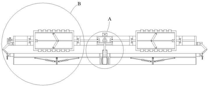
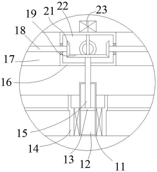
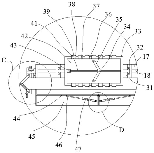
[0026] Such as Figure 1-Figure 5 As shown, the present invention is described in detail. For the convenience of description, the orientations mentioned below are now stipulated as follows: figure 1 The up, down, left, right, front and back directions of the projection relationship itself are consistent. The biomass recovery equipment of the present invention includes a bottom box 14, a top box 16 is arranged on the upper side of the bottom box 14, and a box for holding The storage and discharge device for storing biomass raw materials and facilitating the discharge of equipment, the top rotating ring 57 is arranged on the outer side of the top casing 16, and a top rotating ring 57 is arranged between the top rotating ring 57 and the bottom casing 14 to make the top A distance adjustment device for changing the distance between the box body 16 and the bottom box body 14. A driving device for driving the top box body 16 to rotate is provided on one side of the top rotating ring...


PUM


Abstract

The invention discloses biomass recovery equipment which comprises a bottom box body. A top box body is arranged on the upper side of the bottom box body, a containing and discharging device used forcontaining biomass raw materials and facilitating discharging of the biomass raw materials out of the equipment is arranged in the bottom box body, and a top rotating ring is rotationally arranged onthe outer side of the top box body; and a distance adjusting device for changing the distance between the top box body and the bottom box body is arranged between the top rotating ring and the bottombox body, and a driving device for driving the top box body to rotate is arranged on one side of the top rotating ring. The biomass recovery equipment is simple in structure; according to the equipment, the manner that the heights of an upper machine body and a lower machine body of the equipment can be adjusted is adopted, in the adjusting process, the upper machine body can rotate to fully smashthe biomass raw materials, and the interior of the equipment can be adjusted according to a smashing area; and the equipment can efficiently smash the materials with different heights and different distribution conditions.

Description

technical field [0001] The invention relates to the technical field of renewable energy equipment, in particular to biomass recovery equipment. Background technique [0002] The most common resource regeneration technology is the recovery of biomass. Biomass can be fully ground and crushed by vegetation materials such as straw for uniform granulation. The existing grinding equipment has a single structure and cannot effectively adjust the height. During the grinding process, it is impossible to effectively adjust the grinding area, the grinding is insufficient, and the effective convex top effect cannot be performed during the grinding process, so that the crushing and grinding effect of the biomass during the grinding process cannot be achieved as expected. It greatly reduces the working efficiency of the equipment. Due to the existence of the above shortcomings, the equipment cannot overcome the above shortcomings to achieve efficient processing during the actual work proc...

Claims


Application Information

Patent Timeline
Patent Type & Authority Applications(China)
IPC IPC(8): B02C4/12B02C4/30B02C4/34B02C4/42B02C4/28A01F29/00A01F29/09A01F29/12
CPCA01F29/005A01F29/09A01F29/12B02C4/12B02C4/28B02C4/30B02C4/34B02C4/42B02C2201/066Y02P60/12
Inventor 舒海球
Owner 博兴兴博投资有限公司
Learn More