
Combined structure of ureteroscope catheter and ureter sheath

A combined structure and ureteroscope technology, applied in catheters, urethroscopes, endoscopes, etc., can solve problems such as the inability to observe the discharge of broken stones, increase the pain of patients, and damage human organs

Pending Publication Date: 2020-11-03
YOUCARE TECH CO LTD
View PDF5 Cites 1 Cited by
  • Summary
  • Abstract
  • Description
  • Claims
  • Application Information

AI Technical Summary

Problems solved by technology

In the existing flexible ureteroscopic surgery, the sheathing dilation tube cooperates with the ureteral sheath for sheathing operation, and then the ureteroscopic catheter is inserted into the ureteral sheath to treat the affected area. The crushed stones need to be excreted through the ureteric sheath. At this time, the ureteroscope catheter needs to be withdrawn to operate. However, due to the withdrawal of the ureteroscope catheter, the discharge of the crushed stones cannot be observed, and the broken stones cannot be completely discharged from the body at one time. To ensure the effect of the operation, it is necessary to insert the ureteroscopic catheter multiple times for observation or treatment. This repeated operation of inserting the ureteroscopic catheter increases the pain of the patient, and it is also easy to cause damage to human organs

Method used


Image

  • Combined structure of ureteroscope catheter and ureter sheath
  • Combined structure of ureteroscope catheter and ureter sheath
  • Combined structure of ureteroscope catheter and ureter sheath

Examples


Embodiment Construction

[0045] The present invention will be further described in detail below in conjunction with the accompanying drawings and specific embodiments.

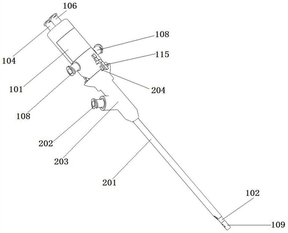
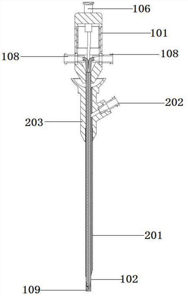
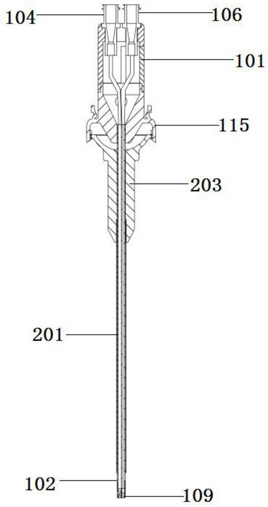
[0046] Such as figure 1 The combined structure of the ureteroscope catheter and ureter sheath shown in -21 includes a tube sheath 201 and a catheter 102 coaxially inserted into the tube sheath 201 .

[0047] One end of the sheath 201 is coaxially fixed in the sheath handle 203, the side of the sheath handle 203 is connected with a stone drainage joint 202 communicating with the sheath 201, the catheter 102 is coaxially inserted into the sheath handle 203, and the sheath 201 includes a large arc tube sheath section 201.1 coaxial with the catheter 102 and a large arc tube sheath section 201.1 fixedly connected to the left and right end faces of the large arc tube sheath section 201.1, the axial direction is parallel to the axial direction of the large arc tube sheath section 201.1 The small arc tube sheath section 201.2, which is the r...


PUM


Abstract

The invention discloses a combined structure of a ureteroscope catheter and a ureter sheath. The combined structure comprises a catheter sheath and a catheter which is coaxially inserted into the catheter sheath and can move front and back in the axial direction of the catheter sheath, a calculus and liquid discharging connector is connected to the side part of the catheter sheath, one end of thecatheter is coaxially fixed into a catheter handle, and a water inlet and instrument channel is formed in the catheter in the axial direction. A water inlet and instrument connector communicating withthe water inlet and instrument channel is arranged on the catheter handle, a catheter cap is fixed at the other end of the catheter, and a guide structure which communicates with the water inlet andinstrument channel and can enable water entering the water inlet and instrument channel to flush and drain towards one side of the catheter handle is arranged in the catheter cap. After sheathing, theureter sheath can be used as a surgical instrument and penetrates into an endoscope in cooperation with a ureteroscope, calculus breaking and discharging operation is performed in cooperation with holmium laser and other instruments through the water inlet and instrument channel connector, and fine calculi fall off from an affected part under the action of a lateral flushing channel of the catheter cap and a lateral water outlet of the catheter cap. The calculi are discharged along with return water through a small arc tube sheath section of a special-shaped sheath tube.

Description

technical field [0001] The invention relates to the technical field of urological surgery equipment, in particular to a combined structure of a ureteroscope catheter and a ureteral sheath. Background technique [0002] In flexible ureteroscopic surgery, the flexible ureteroscope can enter the body through the urethra to observe the lesion and can cooperate with surgical instruments to perform visual surgery in the body. Clinical internal examination and visual surgical treatment require endoscopes with clear images to help doctors improve the accuracy of diagnosis. In the existing flexible ureteroscopic surgery, the sheathing dilation tube cooperates with the ureteral sheath for sheathing operation, and then the ureteroscopic catheter is inserted into the ureteral sheath to treat the affected area. The crushed stones need to be excreted through the ureteric sheath. At this time, the ureteroscope catheter needs to be withdrawn to operate. However, due to the withdrawal of th...

Claims


Application Information

Patent Timeline
Patent Type & Authority Applications(China)
IPC IPC(8): A61B1/307A61B1/018A61B1/12A61B18/24
CPCA61B1/307A61B1/018A61B1/126A61B18/245A61B2218/002A61B2218/007A61B2018/00982
Inventor 王少刚李金平毛业云胡学成李聪张加桥龙刚
Owner YOUCARE TECH CO LTD
Learn More