Diaphragm and sounding device of a sounding device

A sounding device and rubber mixing technology, which can be used in sensors, electrical components, etc., can solve the problems of poor heat and cold resistance of thermoplastic resins, large product distortion, and small steric resistance, and achieve good overall performance and molding consistency. Good, improve the effect of production efficiency

Active Publication Date: 2021-01-22
GOERTEK INC
View PDF4 Cites 0 Cited by
  • Summary
  • Abstract
  • Description
  • Claims
  • Application Information

AI Technical Summary

Problems solved by technology

[0004] However, in the process of realizing the embodiment of the present application, the inventors of the present application found that the above-mentioned technology has at least the following technical problems: the use of high-modulus plastics cannot meet the high-power requirements of the 5G era because of its lightness and thinness. It is difficult to withstand large mechanical vibrations under high temperature conditions, resulting in membrane rupture; thermoplastic resins have poor heat and cold resistance, plastic deformation occurs at high temperatures, and become brittle at low temperatures; silicone rubber is used, although its thermal stability and resilience are poor. It is better, but because of its symmetrical chemical structure, high tacticity, small steric hindrance of symmetrically substituted methyl groups, and relatively low modulus or hardness of silicone rubber, it will cause damping of the material under the premise of meeting the same F0 requirements. Low performance, resulting in larger distortion of silicone rubber diaphragm products
It can be seen that the overall performance of the above-mentioned diaphragms is relatively poor, and cannot meet the overall performance requirements of the sounding device

Method used


Image

  • Diaphragm and sounding device of a sounding device
  • Diaphragm and sounding device of a sounding device
  • Diaphragm and sounding device of a sounding device

Examples


preparation example Construction

[0052] In the present invention, the method for preparing the diaphragm of the sound generating device includes the following steps: mixing the raw materials containing raw rubber and filler reinforcing agent to obtain the mixed rubber; taking the mixed rubber and molding it into Get the diaphragm.

[0053] The present invention also provides a sound generating device, which includes a magnetic circuit system and a vibration system that cooperate with each other, and the vibration system includes the above-mentioned diaphragm.

Embodiment 1

[0056] A vibrating membrane of a sounding device, the vibrating membrane comprises a layer of elastomer layer, wherein the elastomer layer is made of mixed rubber; and the raw materials of the vulcanization accelerator are obtained by mixing, wherein the raw rubber includes polysulfide rubber, and the particle diameter of the filler reinforcing agent is 10nm.

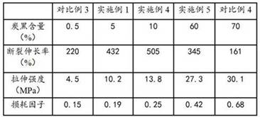
[0057] The filler reinforcing agent adopts carbon black; the content of the filler reinforcing agent is 5% of the total amount of the rubber compound.

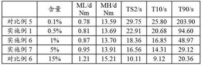
[0058] The vulcanizing agent adopts sulfur, and the vulcanizing accelerator adopts thiuram polysulfide; the content of the vulcanizing agent and the vulcanizing accelerator is 0.5% of the total amount of the rubber compound.

Embodiment 2

[0060] Based on Example 1, the only difference is that the filler reinforcing agent in Example 2 has a particle size of 4 μm.


PUM

PropertyMeasurementUnit
particle diameteraaaaaaaaaa
tensile strengthaaaaaaaaaa
particle diameteraaaaaaaaaa

Abstract

The invention discloses a vibrating membrane of a sounding device and a sounding device. The vibrating membrane includes at least one layer of elastic body layer, wherein the elastic body layer is made of mixed rubber; the mixed rubber is composed of raw rubber It is obtained by kneading the raw materials of filler and reinforcing agent, wherein the raw rubber includes polysulfide rubber, and the particle size of the filler and reinforcing agent is 10nm-10μm. The vibrating membrane obtained by the invention has good comprehensive performance, can work normally under extreme conditions of high and low temperature, can maintain good rigidity, resilience and damping performance, has low distortion, and restores the essence of sound.

Description

technical field [0001] The invention relates to the technical field of acoustic devices, and in particular, the invention relates to a diaphragm of a sound generating device and the sound generating device. Background technique [0002] With the rapid development of the 5G era, electroacoustic devices are gradually developing in the direction of thinner, smarter, higher power, and higher frequency. Consumers require products with higher power, better sound quality, and better performance. Stable and wider frequency response, which requires electro-acoustic devices to develop in the direction of thinning, miniaturization, and high power. The diaphragm is a very important part of the speaker, and its performance directly affects the acoustic performance of the speaker product. [0003] The materials used for the diaphragm of the existing sound generating device mainly include high-modulus plastics (such as PEEK, PAR, PEI, PI, etc.), thermoplastic resins (such as TPU) and sili...

Claims


Application Information

Patent Timeline
Patent Type & Authority Patents(China)
IPC IPC(8): H04R31/00
CPCH04R31/003
Inventor 王翠翠惠冰凌风光李春
Owner GOERTEK INC
Why Eureka
Try Eureka